STRUCTURAL CD3340B/YB4411
11-28
Published 04/07/2015 Control # 569-00
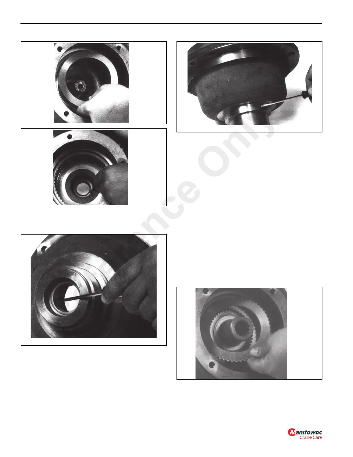
8. Examine the bushing (3, Figure 11-46) in the brake
housing (1) for wear and if found replace it
(Figure 11-54).
9. Examine the journal for wear on the brake housing
(Figure 11-55) where the seal runs. If severely worn,
replace the brake housing.
10. Carefully disassemble the brake driver/clutch assembly
(17-23, Figure 11-46) noting the direction of lockup on
the clutch. The clutch assembly must be assembled with
the arrow pointing in the proper direction for the hoist to
operate properly. Inspect the area on the driver where
the clutch runs. If there is any pitting or spalling on the
driver, it and the clutch must be replaced.
Assembly
1. Assemble the driver and clutch assembly. Make sure
that the clutch is installed correctly.
2. Install a new seal (4, Figure 11-46) into the brake
housing (1), temporarily install the hoist input sun gear,
and slide the brake driver/clutch assembly onto the sun
gear spline. Install the spacer (5) into the housing.
3. Install the stator plates and the friction discs into the
housing starting with a stator plate (Figure 11-56) and
followed by a friction disc (Figure 11-57). Alternate stator
plates and friction discs until all are installed. There is
one more stator plate than friction discs, so you will
finish with a stator plate.
Reference Only

 Loading...


