GROVE 11-27
CD3340B/YB4411 STRUCTURAL
11
Published 04/07/2015 Control # 569-00
4. If one or both of the square seals (8, Figure 11-46)
remain in the bore of the brake housing (1), remove
them.
5. Grasp the brake driver/clutch assembly (items 17
through 23, Figure 11-46) and remove it from the brake
housing.
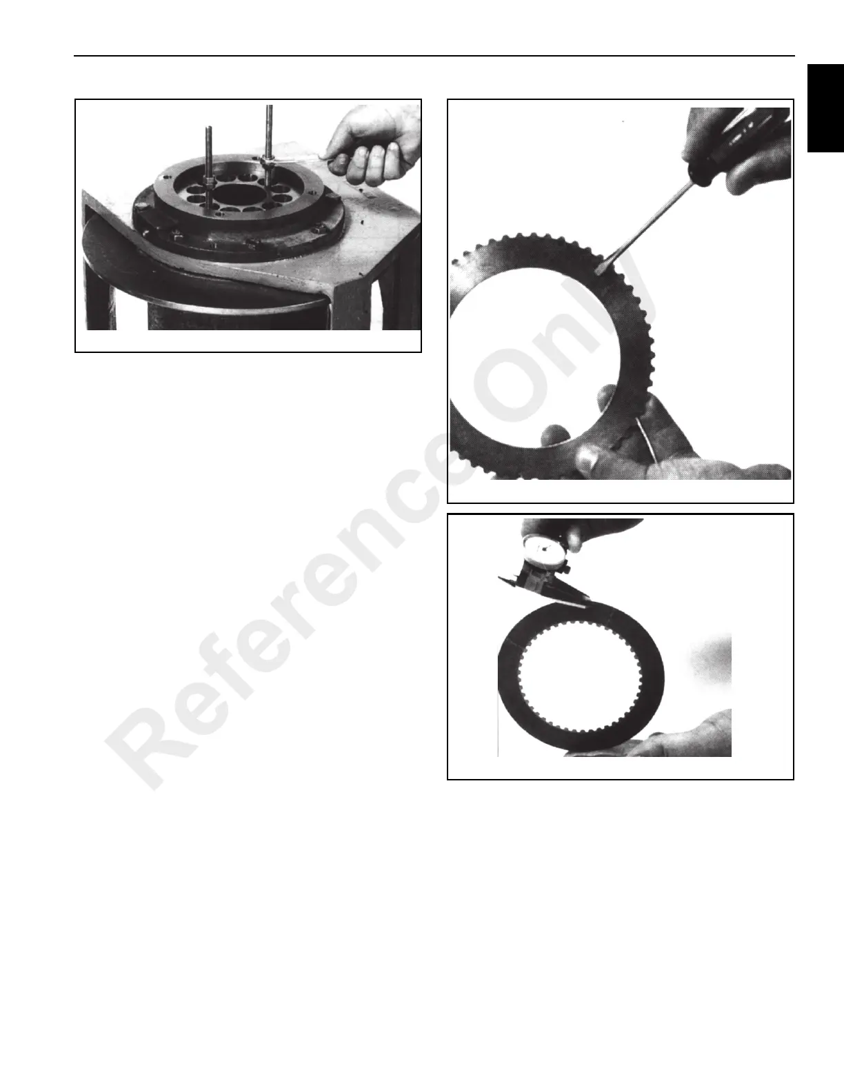
6. Remove the stator plates (7) and friction discs (6) from
the brake housing and check them for excessive wear.
Replace if necessary. Be sure to check the top stator
plate (Figure 11-50) for scoring caused by the removal
tools and polish if necessary. Friction discs (6,
Figure 11-46) should measure (Figure 11-51) no less
than 1.40 mm (0.055 in) thickness and stator plates (7,
Figure 11-46) should measure no less than 1.72 mm
(0.068 in) thickness.
7. Remove the spacer (5, Figure 11-46) from the brake
housing (Figure 11-52). With a hook (Figure 11-53) or
pry bar, remove the seal (4).
Reference Only

 Loading...


