GROVE 4-37
CD3340B/YB4411 HYDRAULIC SYSTEM
Published 04/07/2015 Control # 569-00
6. Remove spacer plate (15).
7. Remove seal (13) from housing (10).
8. Remove output shaft (9) from housing (10).
9. Remove needle thrust bearing (8) from shaft or housing.
10. Reposition the motor in the vice. Clamp across ports as
shown in Figure 4-25. DO NOT clamp on housing.
Excessive clamping pressure on side of housing causes
distortion.
11. Remove four capscrews (1) from mounting flange (3).
These screws were installed with Loctite to hold them in
place.
The screws will require 35 - 45 Nm (300 - 400 lb-in) of
torque to break loose and 11 Nm (100 lb-in) torque to
remove. Do not use an impact wrench on the screws.
This could result in rounded heads or broken sockets.
NOTE: If a torque higher than given above is required to
break the capscrews loose, apply heat according to
the following:
When heated, Loctite partially melts. This reduces
the torque required to remove screw. Use a small
flame propane torch to heat a small area of the
housing where the screws enter. See Figure 4-26.
Be careful not to overheat the housing and
damage the motor. Gradually apply torque to the
capscrew with a socket wrench as heat is applied
for 8 to 10 seconds. As soon as the screw breaks
loose, remove the heat from the housing. Continue
turning the screw until it is completely removed.
Repeat for other capscrews.
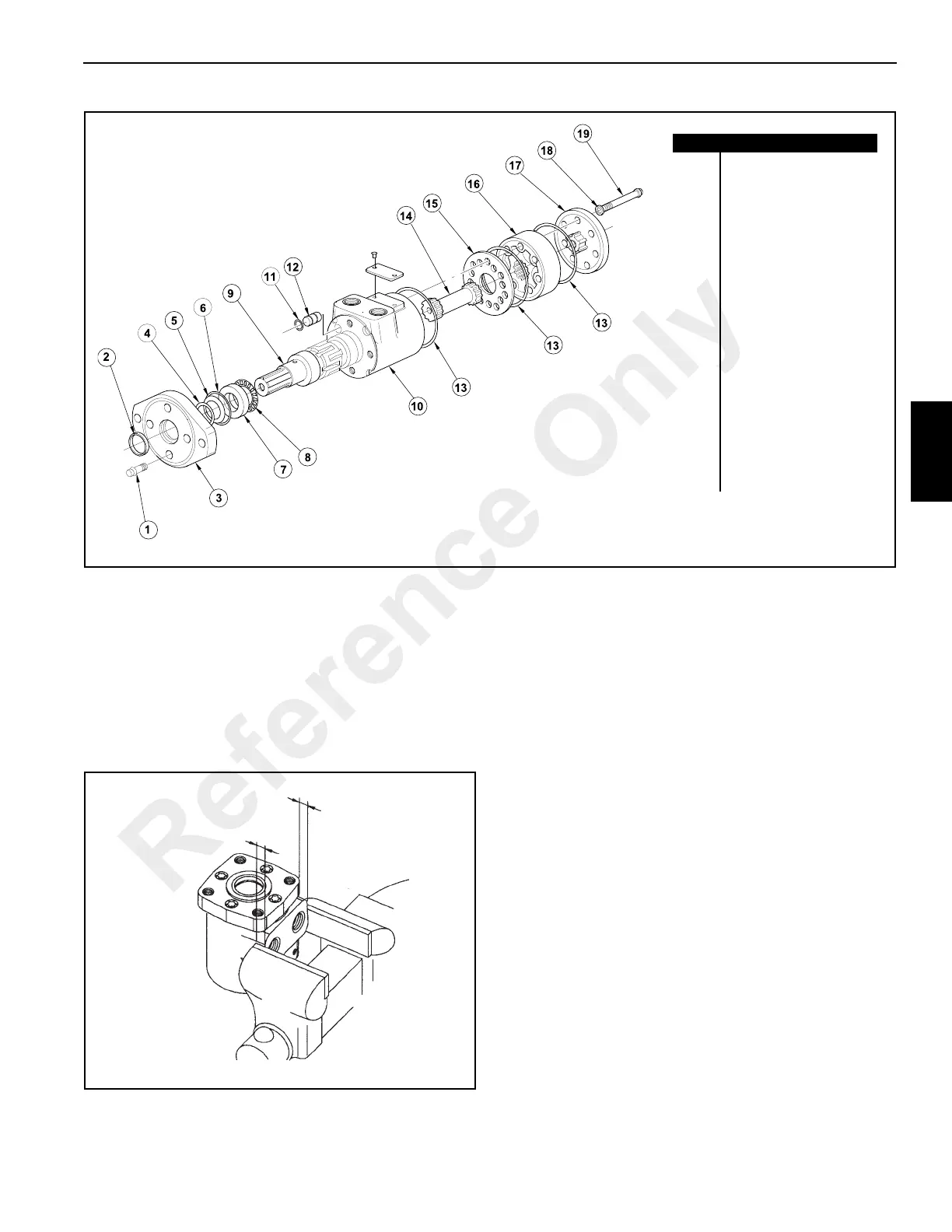
FIGURE 4-24
Item Description
1Screw (4)
2 Exclusion Seal
3 Mounting Flange
4 Backup Ring*
5 Shaft Pressure Seal *
6 Seal*
7 Bearing Race
8 Thrust Needle Bearing
9 Output Shaft
10 Housing
11 O-ring
12 Plug
13 Seal (3)*
14 Drive Shaft
15 Spacer Plate
16 Gerotor Set
17 End Cap
18 Seal Washer (7)*
19 Screw (7)
* Included In Seal Kit
a0949
FIGURE 4-25
a0764
1/2” (13 mm)
1/2” (13 mm)
Reference Only