POWER TRAIN TMS700E SERVICE MANUAL
7-46 Published 01-29-2015, Control # 512-01
clutch release yoke rides up and over the release
bearing (throw-out bearing) while the shaft goes into the
pilot bearing.
5. Install the 12 bolts and washers mounting the
transmission’s clutch housing to the engine flywheel
housing. Tighten the bolts; refer to Fasteners and
Torque Values on page 1-12 for the torque value.
6. Refer to Engine - Installation in this section and install
the engine and transmission.
Clutch Adjustment Procedure
1. Remove the inspection plate from bottom of the clutch
housing.
2. Verify the following:
• Clutch lever is properly installed, the adjusting
screw on clutch pedal adjusting lever is equally
adjusted in either direction.
• The adjusting screw is set to 1.6-3.2 mm
(1/16-1/8 in) wear clearance, as shown,
(Figure 7-29).
• That all rod end bearings and jam nuts on control
rods are tight and have sufficient thread
engagement (4 threads min) on each rod.
• Cable is set to the middle of its adjustment range at
both ends.
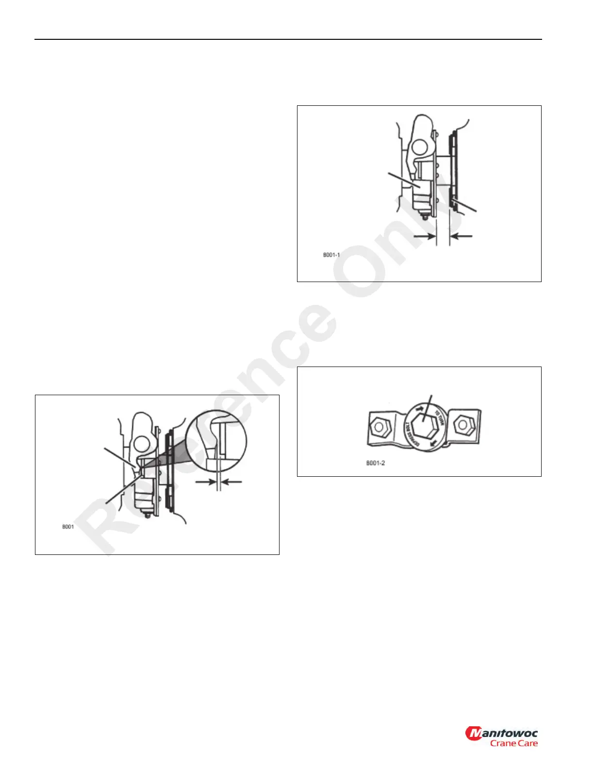
3. Visually check the travel of the release bearing after
working the pedal several times. Measure the distance
between the release bearing and the clutch brake. The
correct distance should be 12.7-14.2 mm (0.500-.560 in)
(Figure 7-30).
4. To adjust, remove cover plate and disassemble grease
hose/fitting inside.
5. Depress clutch and turn adjusting nut. Clockwise moves
the bearing toward transmission, (Figure 7-31)
NOTE: 2-1/3 rotations = 3 mm (1/8 in)
6. Clutch brake squeeze should begin 12.7-25.4 mm (0.50-
1.00 in) above the end of pedal stroke. Insert a 0.25 mm
(0.010 in) feeler gauge between the release bearing and
the clutch brake (Figure 7-32). Press the pedal down to
clamp the gauge. If the gauge does not clamp, adjust
linkage to achieve clutch brake squeeze then repeat this
step.
FIGURE 7-29
Yoke Tips
Bearing Wear Pads
3.2 mm (1/8 in)
FIGURE 7-30
Release Bearing
Clutch Brake
12.7-14.2 mm (.50-.56 in)
Transmission
Reference Only

 Loading...


