Grove Published 01-29-2015, Control # 512-01 8-7
TMS700E SERVICE MANUAL UNDERCARRIAGE
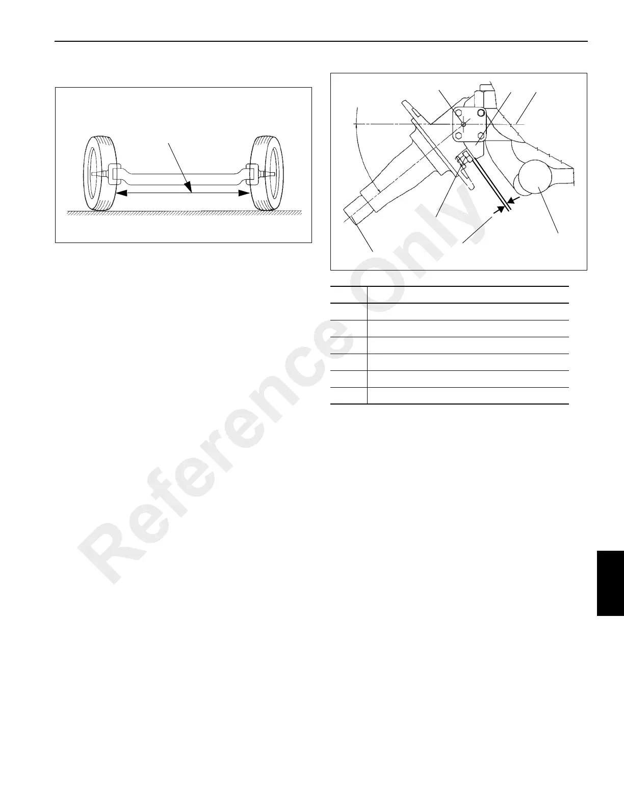
Toe-In Adjustment
Toe-in (see Figure 8-3) is having the wheels of a steerable
axle closer together in the front than in the rear. Toe-in is
necessary for both tire wear and to keep the wheels from
weaving side to side.
1. Position the wheels straight ahead.
2. Loosen the clamps on the tie rods.
3. Adjust the tie rod as needed to provide between 0.0 to
1.5 mm (0 to 0.06 in) of toe-in for each wheel. Double
check to ensure both wheels have the correct toe-in.
4. Position the clamps on the tie rod beams so that they
clear the axle when the wheels are turned. Tighten the
clamps and recheck toe-in measurement.
Axle Stop Settings
1. Remove and discard the axle stop bolts on the last front
axle.
2. Adjust the axle stop bolts (see Figure 8-4) on the first
front axle, the bolts should be adjusted in or out as
needed to obtain a measurement of 3.0 mm (0.12 in)
minimum from the rigid axle stop to the top of the bolt
head (see Figure 8-4).
Drag Link Installation and Axle Synchronization
NOTE: All detail numbers are in reference to Figure 8-5.
1. Assemble front relay arm (Detail #9) and drag link (Detail
#7). Install the assembly on the carrier frame.
2. Attach rear relay arm (Detail #8) to the opposite end of
drag link (Detail #7) and then install the relay arm on the
carrier frame.
NOTE: It is acceptable to use a 21/64 drill bit as the rig
pin(s).
3. Install a 8.33 mm (0.328 in) diameter rig pin through the
front relay arm mounting bracket and the front relay arm.
Adjust drag link (Detail #7) so that a 8.33 mm (0.328 in)
rig pin can be installed through the rear relay arm
mounting bracket and the rear relay arm.
4. Check that the front wheels are aligned to the straight
ahead position by using a straight edge long enough to
lay across the wheel mounting surfaces of both front
axles. Adjust drag links (Detail #5) to fit between the
relay arms (Details #8 and #9) and the axle steer arms.
5. Check the position of the pitman arm on the steering
gearbox and adjust if necessary. Attach drag link (Detail
#6) to the pitman and adjust its length as needed to fit
between the pitman arm and the front relay arm (Detail
#9) while keeping the pitman arm position fixed.
Tire front distance is less
than tire rear distance as
measured on the axle center
line. (1.5 mm or 0.06 in
difference)
FIGURE 8-3
Item Description
1 Spindle
2 King Pin Center
3 Rigid Axle Stop
4 C/L Of Axle
5Tie Rod
6 Axle Stop Bolt
Cramp Angle
3.0 mm (0.12 in)
minimum
FIGURE 8-4
1
6
5
4
3
2
Reference Only

 Loading...


