UNDERCARRIAGE TMS700E SERVICE MANUAL
8-36 Published 01-29-2015, Control # 512-01
3. The dual thread release bolt which reduces the travel of
the release bolt by a factor of 2.4 in a 76 mm (3.00 in)
stroke unit, for instance, the parking spring is fully caged
when the release bolt is up approximately 33 mm (1.3 in)
from the run position (Figure 8-37). After caging,
completely exhaust air from the spring chamber.
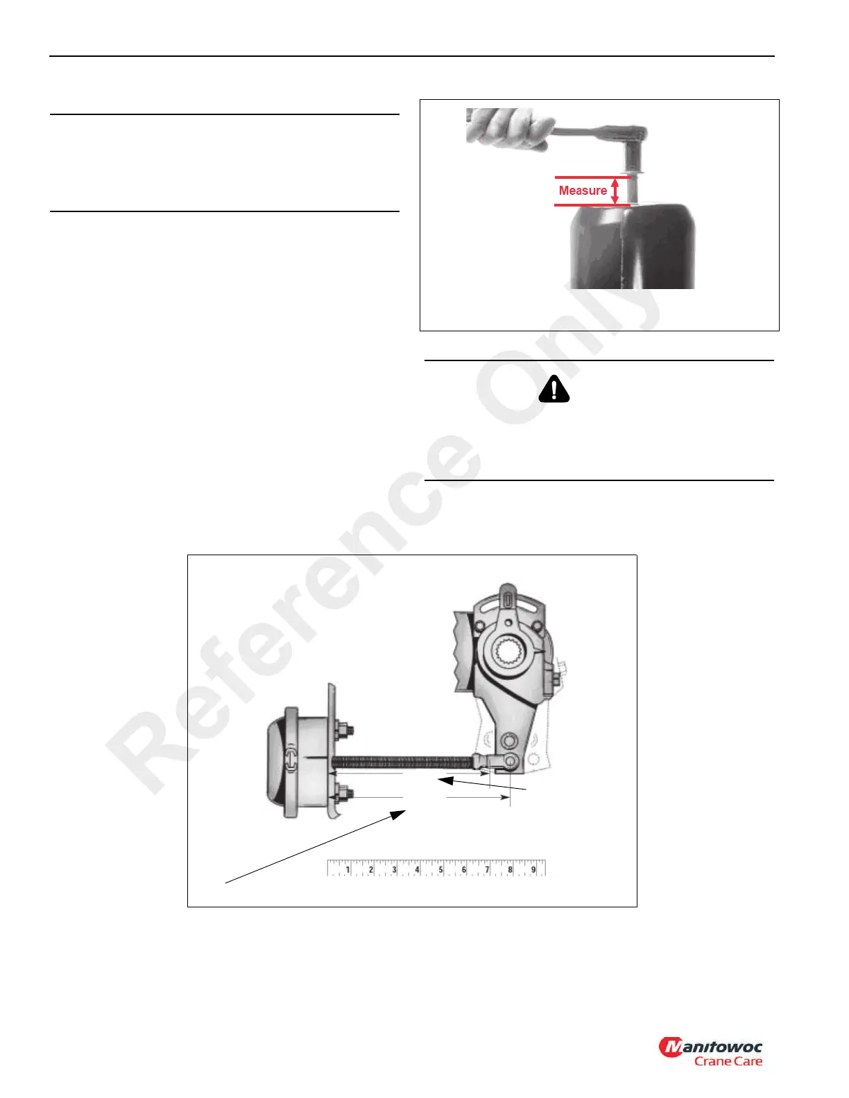
4. Measure the distance from the center of the large clevis
to the air chamber mounting face with the brake fully
released. This is dimension “X” in (Figure 8-38)
CAUTION
Do not exceed the length stated in step 3 and do not
exceed 68 Nm (50 lb-ft) torque on release bolt at any time
or damage may occur which could prevent any further
correct manual release of the spring brake chamber.
DANGER
There are no serviceable parts inside the spring brake
chamber. Never attempt to disassemble the spring brake
chamber as serious personal injury could result from
accidental sudden release of the high energy spring.
Y
7093-6
FIGURE 8- 38
X
(Fully Retracted)
(Drum Contact Using a Lever
Reference Only
 Loading...


