HYDRAULIC SYSTEM TMS700E SERVICE MANUAL
2-24 Published 01-29-2015, Control # 512-01
6. With the boost switch on, attempt to hoist up with the
engine running at full RPM. Adjust the main directional
control valve hoist up, port relief B, to 241 ± 4 bar (3500
± 50 psi).
7. With the boost switch on, attempt to hoist down with the
engine running at full RPM. Adjust the main directional
control valve hoist down, port relief A, to 241 ± 4 bar
(3500 ± 50 psi).
8. Reconnect the hose to port A of the hoist motor control
valve and reconnect the hoist brake release line on the
hoist.
9. If the auxiliary hoist is installed, repeat steps 3 through 8
for the auxiliary hoist and its port reliefs.
10. Completely retract the lift cylinder, attempt to lift down
with the engine running at full RPM. The gauge should
read 138 + 48/-0 bar (2000 +700/-0 psi). This relief
valve is non-adjustable.
11. Completely retract the boom. Try to telescope in with
engine running at full RPM. Adjust the main directional
control valve telescope, port B relief, to 241 ± 4 bar
(3500 ± 50 psi).
12. Completely extend the boom. Try to telescope out with
engine running at full RPM. Adjust the main directional
control valve telescope, port A relief, to 186 ± 4 bar
(2700 ± 50 psi).
13. Remove pressure gauge from the load sense test port
and reinstall cap.
Procedure for Checking Main Directional
Control Valve Pilot Supply Pressure
1. Remove cap and install pressure gauge on pilot supply
test port per Figure 2-8.
2. Adjust the pressure reducing cartridge located in the
inlet of the hoist/lift/telescope directional control valve to
22 to 31 bar (325 to 450 psi). Turn adjustment clockwise
to increase or counterclockwise to decrease the
pressure setting.
3. Remove pressure gauge from the pilot supply test port
and reinstall cap.
Procedure for Checking Swing Brake Pilot
Supply Pressure
1. Remove and install pressure gauge on the swing brake
pilot supply valve test port per Figure 2-9.
2. Adjust pressure reducing valve cartridge to 17
+4/-0 bar
(250 +50/-0 psi). At idle, pressure should read a
minimum of 17 bar (250 psi) to ensure brake is released
for swing operation at idle.
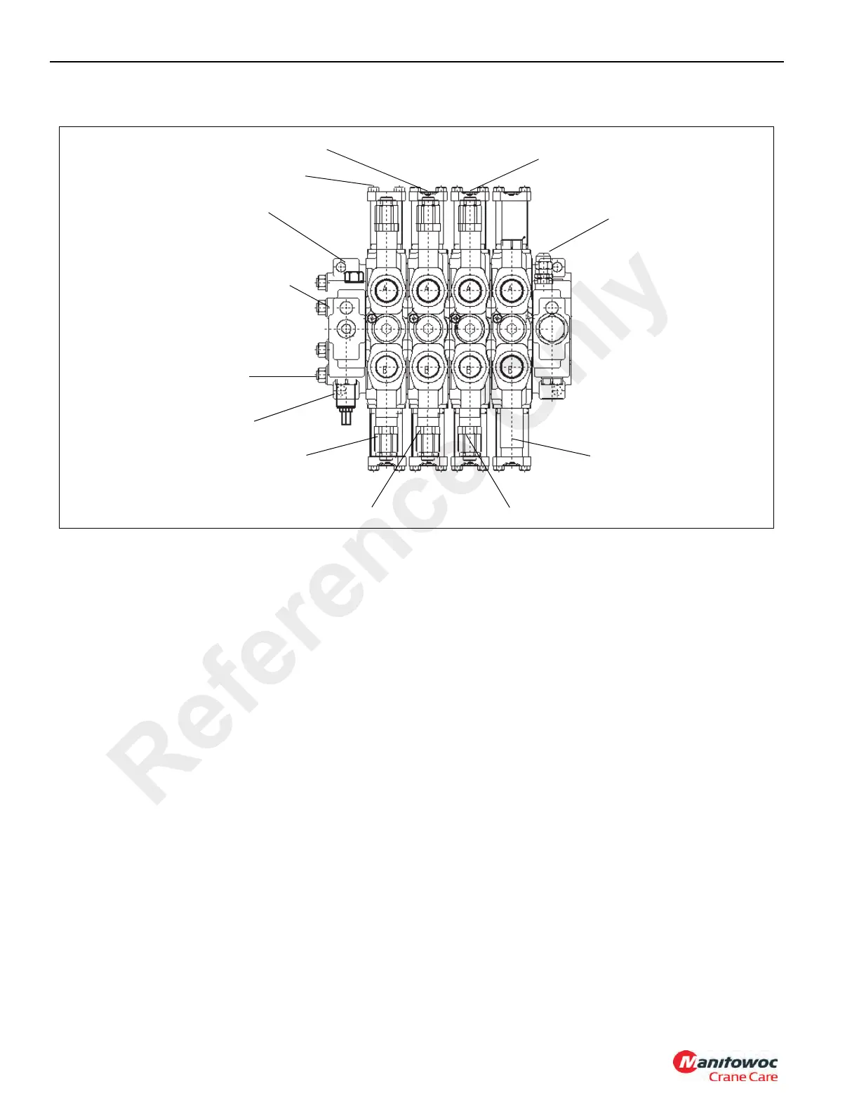
FIGURE 2-8
Lift Down Port Relief
Aux Hoist Up Port Relief
Main Hoist Up Port Relief
Load Sense Relief
Telescope Extend Port Relief
Aux Hoist Down Port Relief
Main Hoist Down Port Relief
Load Sense Relief Test Port
Pilot Supply Test Port
Inlet Gauge Port
Telescope Retract Port Relief
Pilot Supply Pressure
Reducing Cartridge
Reference Only

 Loading...


