SET-UP AND INSTALLATION MLC650 VPC-MAX™ OPERATOR MANUAL
4-28
Published 04-06-18, Control # 231-14
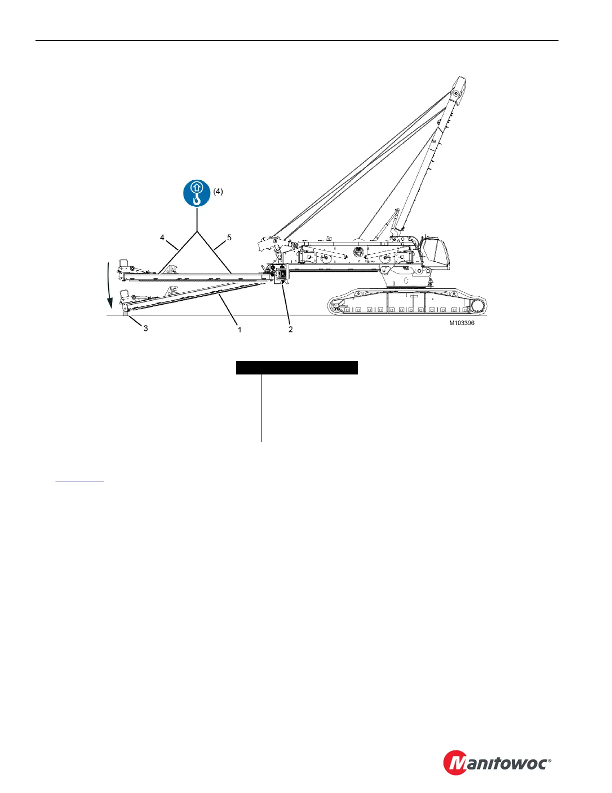
See Figure 4-27 for the following procedure.
16. With the VPC-MAX
beam (1) pinned to the actuator (2)
and still attached to the assist crane, lower the beam
onto the blocking (3).
17. Allow the rear pendants (4) to go slack so the beam is
supported only by the blocking and the actuator.
18. Detach the forward pendants (5) from the beam.
19. Secure the forward pendants to the rear pendants so the
forward pendants cannot swing freely.
FIGURE 4-27
Item Description
1 VPC-MAX Beam
2Actuator
3 Blocking
4 Rear Pendant (qty 2)
5 Forward Pendant (qty 2)