VMS4SE(Vibration Monitor)
REF NO: mVMA/om/101
Issue No: 01
Digit -1 (Left Most Alpha Numeric
Digit) to Digit -6 (Right Most Alpha
Numeric Digit)
Refer
Table
50and
Table
51and
note
Channel – 17 ASCII code for
Digit -1 (Left Most Alpha Numeric
Digit) to Digit -6 (Right Most Alpha
Numeric Digit)
Channel – 18 ASCII code for
Digit -1 (Left Most Alpha Numeric
Digit) to Digit -6 (Right Most Alpha
Numeric Digit)
Channel – 19 ASCII code for
Digit -1 (Left Most Alpha Numeric
Digit) to Digit -6 (Right Most Alpha
Numeric Digit)
Channel – 20 ASCII code for
Digit -1 (Left Most Alpha Numeric
Digit) to Digit -6 (Right Most Alpha
Numeric Digit)
Channel – 21 ASCII code for
Digit -1 (Left Most Alpha Numeric
Digit) to Digit -6 (Right Most Alpha
Numeric Digit)
Channel – 22 ASCII code for
Digit -1 (Left Most Alpha Numeric
Digit) to Digit -6 (Right Most Alpha
Numeric Digit)
Channel – 23 ASCII code for
Digit -1 (Left Most Alpha Numeric
Digit) to Digit -6 (Right Most Alpha
Numeric Digit)
Channel – 24 ASCII code for
Digit -1 (Left Most Alpha Numeric
Digit) to Digit -6 (Right Most Alpha
Numeric Digit)
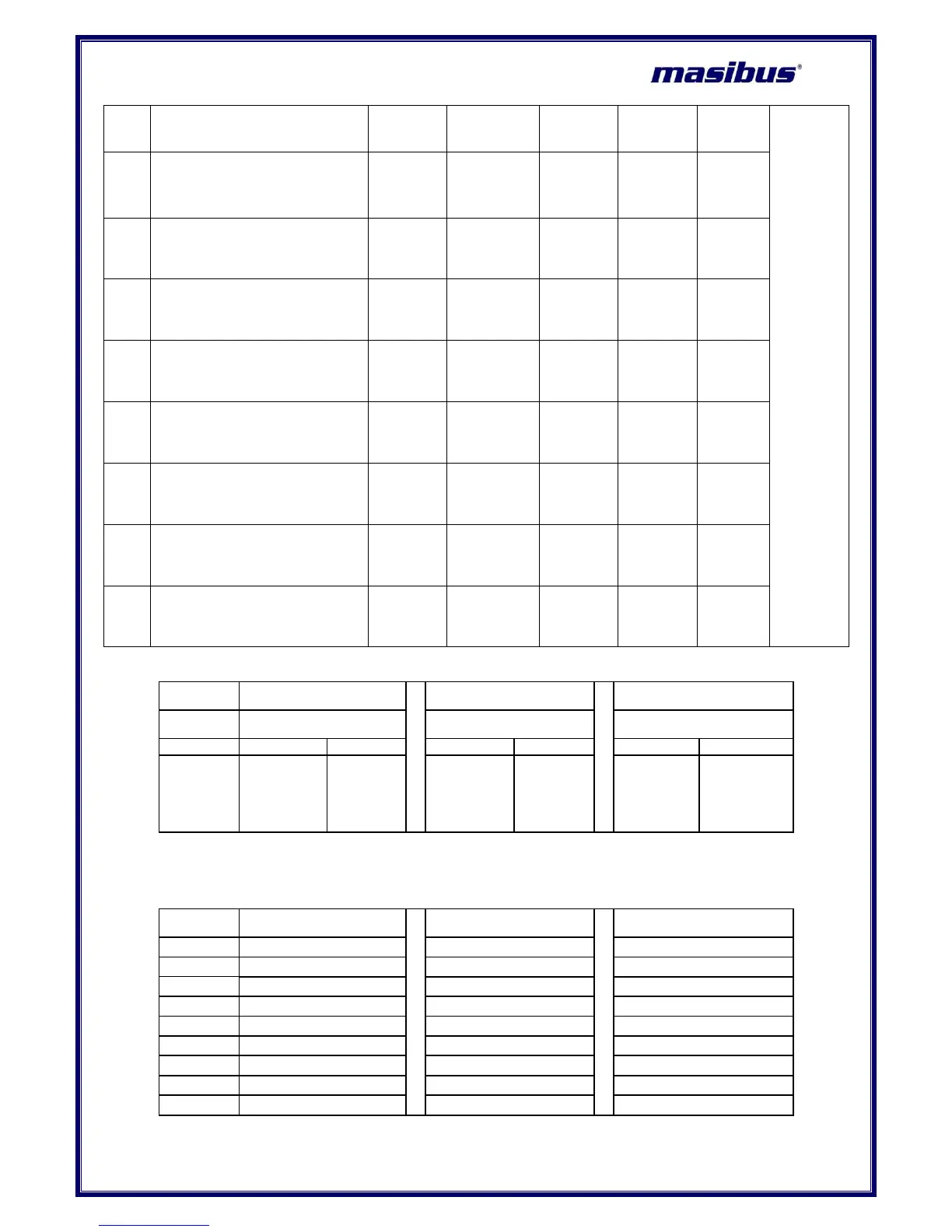
Table 50 Byte arrangement for Programmable Display
Programmable Display for
Channel No. 1
Programmable Display for
Channel No. 1
Programmable Display for
Channel No. 1
ASCII Code
for Left Most
Digit
(Digit No. 1)
ASCII Code
for
Digit No. 2
ASCII Code
for
Digit No. 3
ASCII Code
for
Digit No. 4
ASCII Code
for
Digit No. 5
ASCII Code
for Right Most
Digit
(Digit No. 6)
Above mentioned bit arrangement is applicable to other channels as explained next.
Table 51 Parameters for Programmable Display for other channels
Modbus Address for
Digit 1 and Digit 2
Modbus Address for
Digit 3 and Digit 4
Modbus Address for
Digit 5 and Digit 6
 Loading...