Routing Matrox Iris GTR auxiliary output signals 113
Routing Matrox Iris GTR auxiliary output
signals
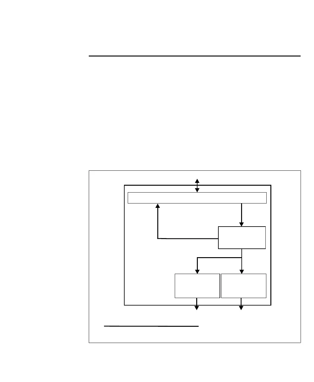
There are three ways to route a Matrox Iris GTR auxiliary output signal:
• Route a Matrox Iris GTR auxiliary output signal to an auxiliary input signal; to
do so, see Routing a Matrox Iris GTR auxiliary output signal to an auxiliary input
signal subsection of the Routing input signals to Matrox Iris GTR section, earlier in
this appendix.
• Route a Matrox Iris GTR auxiliary output signal to a third-party device.
• Route Matrox Iris GTR auxiliary intensity control signal and output signal 0
(trigger) to a lighting controller (for example, the Advanced Illumination inline
control system).
o
Equivalent circuit only
Matrox Iris GTR
Matrox camera connector
Output
router
1
1 A breakout board switch setting controls the routing of an output
to an input.
Third-party device
Output
connector
Third-party device
(lighting controller)
ICS3
connector