Connecting to the auxiliary I/O interface 35
Connecting to the auxiliary I/O interface
Matrox Iris GTR has an auxiliary I/O interface with 7 optically isolated auxiliary
signals. Four are inputs that support sinking and sourcing configurations and can
receive 24 V. Three are outputs that support sinking configurations and operate
at up to 24 V nominal; you could connect one of the outputs in a sourcing
configuration, but the other two outputs would no longer be available. Matrox
Iris GTR also has an analog intensity (dimming) control signal, which is discussed
in the Connecting a light controller and the analog intensity control signal section
later in this chapter.
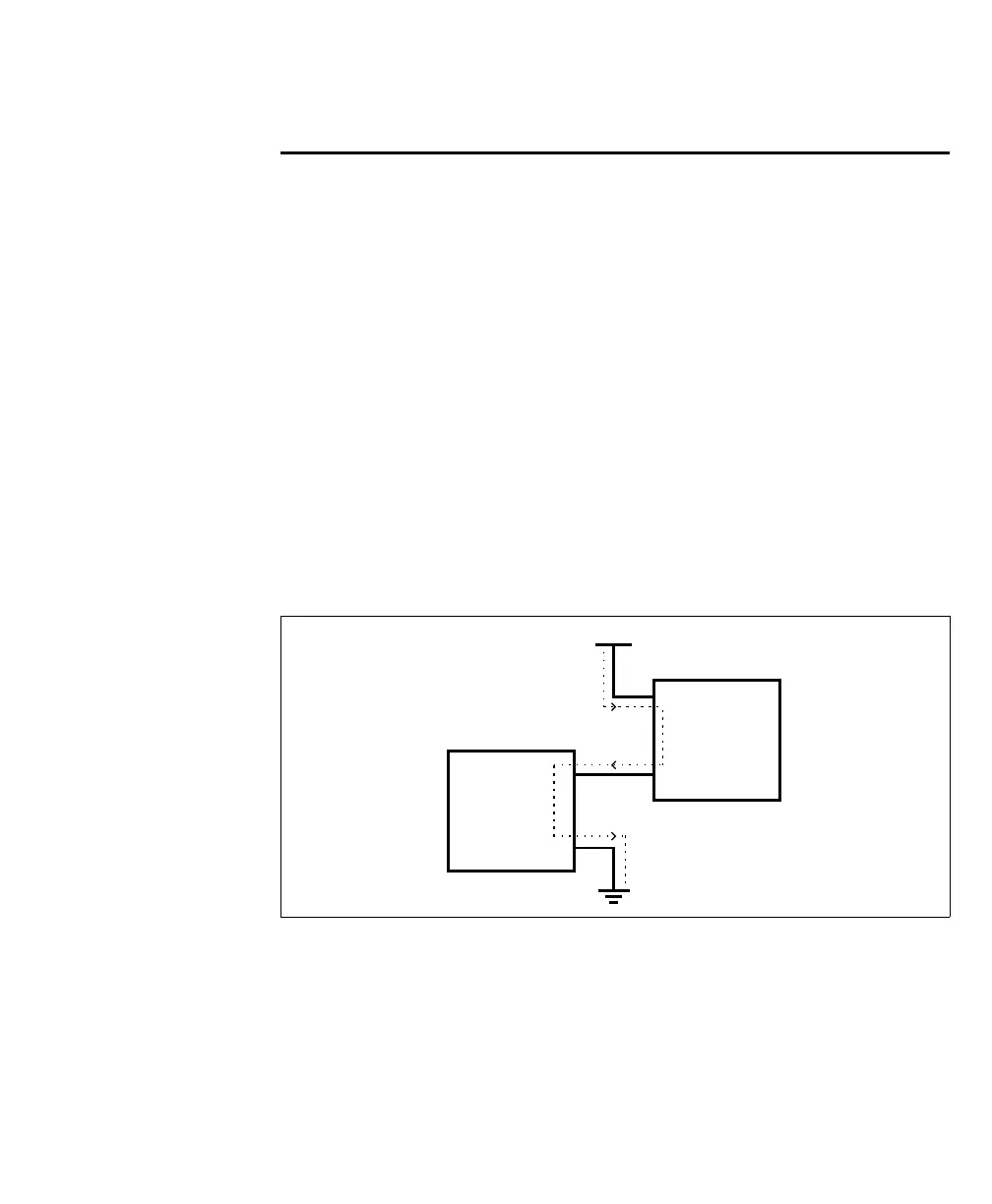
Note that sinking and sourcing concepts refer to the conventional current flow,
which means current flows from the positive potential towards the negative
potential. A sinking device provides a path to sink current towards ground or to
the return path; a sinking device does not provide power. A sourcing device
provides a path that sources current; it provides a path from the power source. In
the following diagram, the device on the right is the sourcing device, and the device
on the left is the sinking device.
When setting up auxiliary I/O, be aware that you need to configure these pins on
the software side as well. If you are using Matrox Design Assistant, refer to the
Connecting to your Matrox Iris GTR as your runtime platform section of the Matrox
Iris GTR appendix in the Matrox Design Assistant help file for this information. If
you are using MIL, refer to Matrox Iris GTR connectors and signal names section
of the Matrox Iris GTR appendix in the MIL help file
Equivalent circuit only
Vcc
Sourcing
device
Sinking
device
+
+
-
-