138 Appendix F: The Matrox Iris GTR breakout board
IN_COM_TERM switch
The IN_COM_TERM switch (SW6[4]) determines whether
AUX_OPTOIND_IN_COMMON is provided externally, through the input
connector’s IN_COM wire-terminal, or through the Matrox Iris GTR
breakout board.
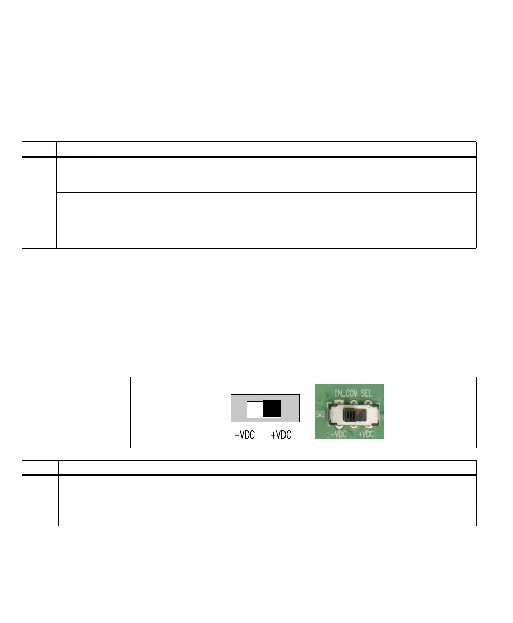
IN_COM selector switch
The IN_COM selector switch (SW2) allows you to change whether the auxiliary
input signals of your Matrox Iris GTR are sinking or sourcing when the common
return path or voltage source is provided by the Matrox Iris GTR breakout board
(when the IN_COM_TERM switch (SW6[4]) is enabled).
❖ Note that the IN_COM selector switch (SW2) is only effective when the
IN_COM_TERM switch (SW6[4]) is enabled (ON).
Switch State Description
SW6[4] ON Specifies that the smart camera’s AUX_OPTOIND_IN_COMMON is provided internally and enables the IN_COM selector
switch (SW2).The IN_COM selector switch (SW2) determines whether the auxiliary input signal is expected to be sourcing or
sinking.
OFF Specifies that the smart camera’s AUX_OPTOIND_IN_COMMON is provided externally and disables the IN_COM selector
switch (SW2). Connect the input connector’s (J5) IN_COM wire-terminal to either a voltage source or return path for your
circuit, respectively, and connect the IN wire-terminal of an auxiliary input signal to the output signal of the third-party device.
If creating an electrically isolated circuit with a third-party device, see Connecting a sinking Matrox Iris GTR auxiliary output
signal to a sourcing input with a different voltage source subsection, previously in this appendix.
Switch Description
-VDC Specifies that your Matrox Iris GTR breakout board will connect the smart camera’s AUX_OPTOIND_IN_COMMON to -VDC, providing
the electrical return path for all auxiliary input signals.
+VDC Specifies that your Matrox Iris GTR breakout board will connect the smart camera’s AUX_OPTOIND_IN_COMMON to +VDC,
providing the voltage source for all auxiliary input signals.