Routing Matrox Iris GTR auxiliary output signals 117
Connecting a sinking Matrox Iris GTR auxiliary output signal to a sourcing
input with a different voltage source
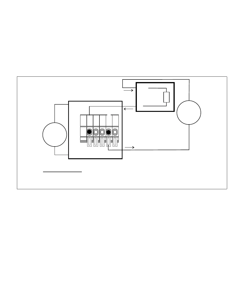
If connecting to a sourcing input of a third-party device which requires less than
24 V, then your Matrox Iris GTR breakout board and your third-party device
must each have their own voltage source. In addition, set the OUT_COM selector
switch (SW3) to OPEN. Then, connect the output connector (J6) to your
third-party device as follows:
[
Equivalent circuit only
24V
+
–
Matrox Iris GTR breakout board
Sinking configuration
-VDC
+VDC
IN
Sourcing device
COM
Input
Sensing
12V**
+
–
OUT_COM
*
OUT0
Output connector (J6)
* In this example, the OUT_COM selector switch (SW3) is set to OPEN; therefore the
OUT_COM wire-terminal is connected.
** The third-party device's power source could be up to 24 V.