116 Appendix F: The Matrox Iris GTR breakout board
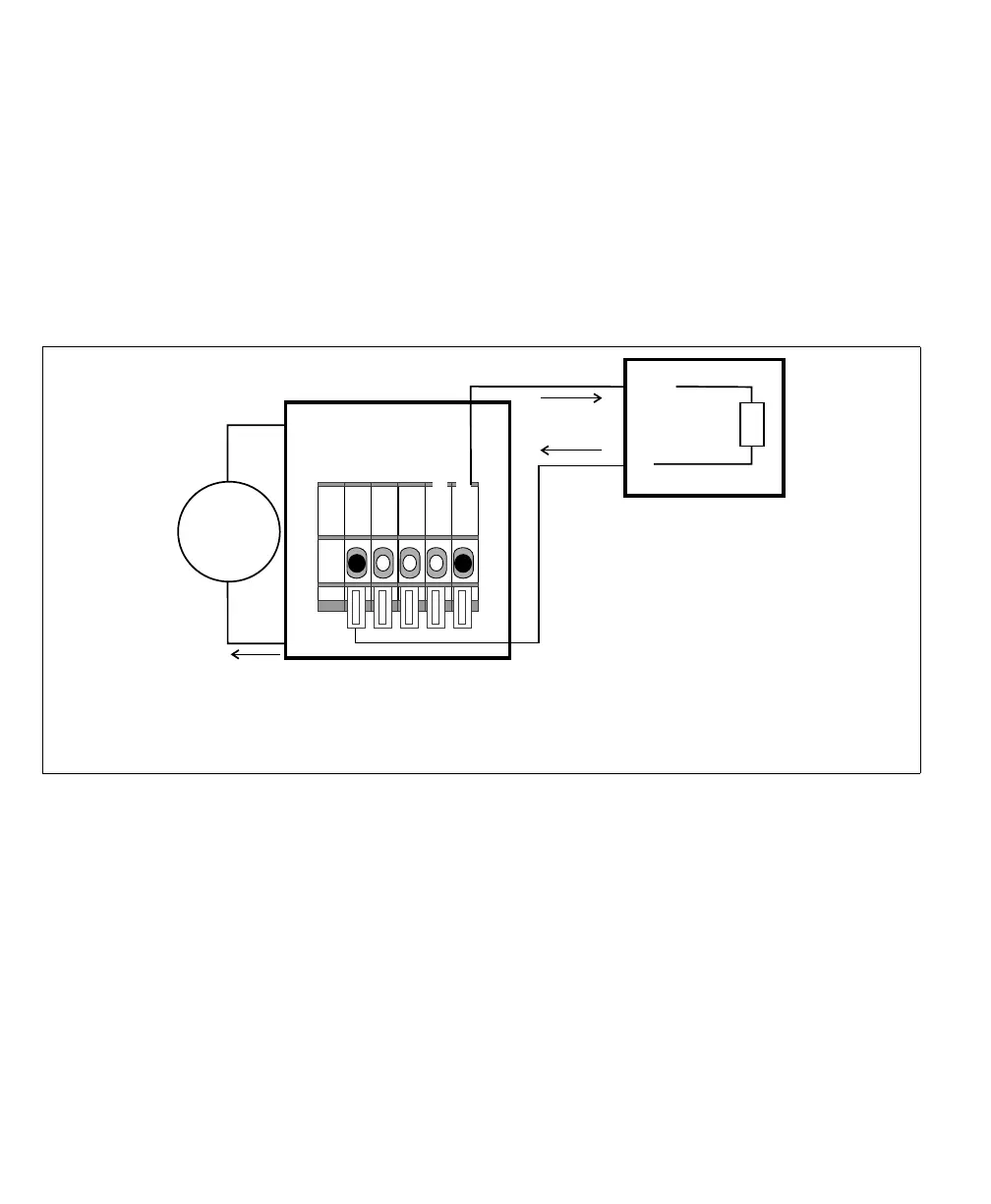
Connecting a sinking Matrox Iris GTR auxiliary output signal to a sourcing
input of a device
If connecting to a sourcing input of a third-party device, the output common
should provide a common return path for the circuit. If the device doesn’t need
to be electrically isolated, you can use the common return path through the Matrox
Iris GTR breakout board (internally); to do so, set the OUT_COM selector
switch (SW3) to -VDC. Then, connect the output connector (J6) to your
third-party device as follows:
❖ Note however, if connecting to a device that needs to remain electrically isolated,
see Connecting a sinking Matrox Iris GTR auxiliary output signal to a sourcing input
with a different voltage source subsection, instead.
Above, the common terminal of the third-party device is connected to the
+VDC_OUT wire-terminal as a voltage source; however, the third party-device
could have used any other voltage source. Each of the auxiliary output signals can
only sink up to 50 mA of current.
Equivalent circuit only
24V
+
–
IN
Sourcing device
COM
Input
Sensing
* In this example, the OUT_COM selector switch (SW3) is set to -VDC, so the
OUT_COM wire-terminal is not externally connected.
Matrox Iris GTR breakout board
Sinking configuration
-VDC
+VDC
max 150 mA
OUT_COM
+VDC_OUT
OUT0
Output connector (J6)