136 Appendix F: The Matrox Iris GTR breakout board
Output-to-input bypass switches
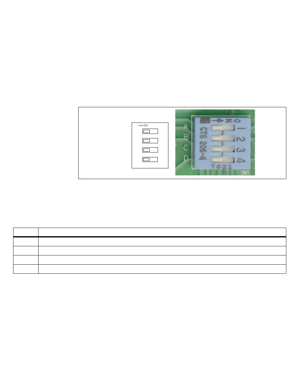
The output-to-input bypass switches (SW5[1] to SW5[4]) allow you to reroute a
Matrox Iris GTR auxiliary output signal to a Matrox Iris GTR auxiliary input
signal.
❖ When creating an output-to-input bypass, enable the pullup for the auxiliary
output signal using the corresponding output pullup resistor switch (SW6[1] -
SW6[3], respectively), if required.
Each auxiliary input signal should have only one input source. For example, when
an auxiliary output signal is re-routed to an input signal, it should always be the
only source of input for that signal, and not have to compete with the signal from
a third-party device or a Matrox Iris GTR breakout board push button.
1
2
3
4
Output to input
bypass switches
OFF/ON
OUT2 → IN6
OUT1 → IN5
OUT0 → IN4
OUT0 → IN3
Switch Description (ON)
SW5[1] Routes the Matrox Iris GTR AUX_OPTOIND_OUT2 signal to the AUX_OPTOIND_IN6 signal.
SW5[2] Routes the Matrox Iris GTR AUX_OPTOIND_OUT1 signal to the AUX_OPTOIND_IN5 signal.
SW5[3] Routes the Matrox Iris GTR AUX_OPTOIND_OUT0 signal to the AUX_OPTOIND_IN4 signal.
SW5[4] Routes the Matrox Iris GTR AUX_OPTOIND_OUT0 signal to the AUX(TRIG)_OPTOIND_IN3 signal.