Open-wire connectors reference 129
Each auxiliary output signal should have only one destination. For example, when
the auxiliary output signal is connected to a third-party device through the output
connector, it should not also be re-routed to an auxiliary input signal or to the
ICS3 connector. This helps prevent signal interference, which could cause issues
with connected devices.
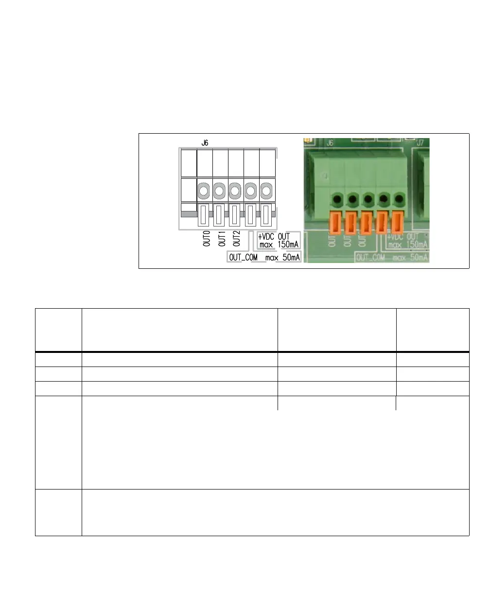
The pinout for the output connector (J6) is as follows:
Wire-
terminal
Description Matrox Iris GTR signal sent Routed through the
Matrox Iris GTR
breakout board’s
camera connector
OUT0 Auxiliary signal 0 (output). AUX_OPTOIND_OUT0 Violet
OUT1 Auxiliary signal 1 (output). AUX_OPTOIND_OUT1 Red/Blue
OUT2 Auxiliary signal 2 (output). AUX_OPTOIND_OUT2 White
OUT_COM Auxiliary signal (output) common. AUX_OPTOIND_OUT_COMMON Brown
Note that, this wire-terminal is shared among the three auxiliary output signals.
This wire-terminal is used to connect to a return path for the auxiliary output signals when connected to a sourcing input of a
third-party device. Alternatively, this wire-terminal can connect to a sinking input, while one of the OUT wire-terminals connects
to a voltage source, to provide a sourcing output (up to a maximum of 50 mA); in this case, only one auxiliary output signal is
available.
In addition, if the OUT_COM selector switch (SW3) is set to -VDC, this wire-terminal should remain disconnected. Instead, your
Matrox Iris GTR breakout board will provide the output common signal.
+VDC_OUT +VDC supply up to a maximum of 150 mA.
This wire-terminal can provide a voltage source to third party devices; you can also externally connect this wire-terminal to one
of the auxiliary output signals if it should be a sourcing output (discussed previously). Note that, If you connect this wire-terminal,
you cannot create an isolated circuit.