134 Appendix F: The Matrox Iris GTR breakout board
Each LED has two states: on and off, where on denotes activity on the monitored
signal. Each LED is named and listed with its board label as follows.
Matrox breakout board
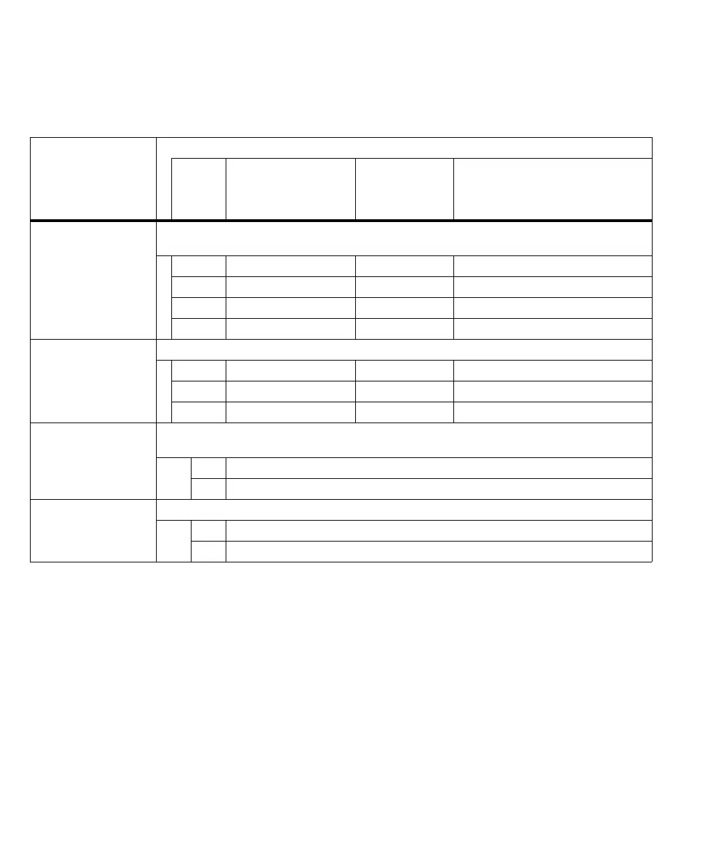
LED name
Description
Board
label
Associated Matrox
Iris GTR signal
Routed through the
Matrox Iris GTR
breakout board’s
camera connector
Description when the LED is On
A. Input LEDs Reports whether there is activity on each Matrox Iris GTR auxiliary input signal, regardless of whether it comes
from a push button, rerouted auxiliary output signal, or connected third-party device.
DS9 AUX(TRIG)_OPTOIND_IN3 Pink Activity on auxiliary signal 3 (input).
DS7 AUX_OPTOIND_IN4 Red Activity on auxiliary signal 4 (input).
DS3 AUX_OPTOIND_IN5 Black Activity on auxiliary signal 5 (input).
DS2 AUX_OPTOIND_IN6 Gray Activity on auxiliary signal 6 (input).
B. Output LEDs Reports whether there is activity on each Matrox Iris GTR auxiliary output signal.
DS8 AUX_OPTOIND_OUT0 Violet Activity on auxiliary signal 0 (output).
DS6 AUX_OPTOIND_OUT1 Red-blue Activity on auxiliary signal 1 (output).
DS5 AUX_OPTOIND_OUT2 White Activity on auxiliary signal 2 (output).
C. On-board input
common LED
Reports whether the auxiliary input signals are sourcing the current (that is, the IN_COM wire-terminal is internally
or externally connected to a voltage source).
DS4 ON Specifies that the auxiliary input signals are sourcing the current.
OFF Specifies that the auxiliary input signals are sinking the current.
D. Main power status LED Reports whether the Matrox Iris GTR breakout board has power from its power connectors (J2/J3).
DS1 ON Specifies that Matrox Iris GTR breakout board has power.
OFF Specifies that Matrox Iris GTR breakout board does not have power.