38 Chapter 2: Powering and connecting to your Matrox Iris GTR
When the auxiliary output signal is attached to a device, the following can be
observed:
Connecting to a
digital device that
requires two
predictable voltage
levels to operate
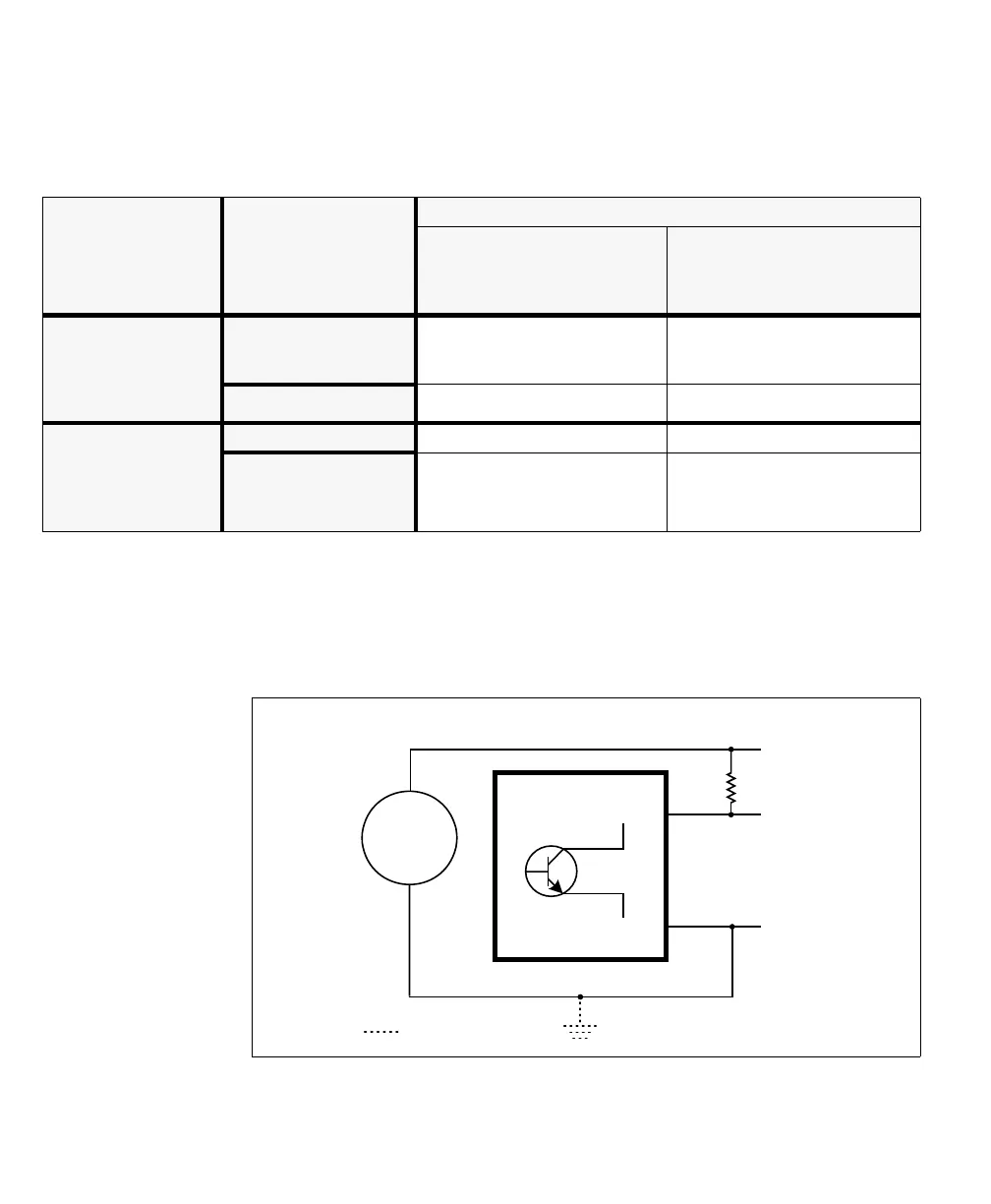
The auxiliary output signals can, therefore, only present one predictable voltage
level for a given configuration: a low voltage level in a sinking configuration or a
high voltage level in a sourcing configuration. Their other output state is, by
default, floating. So, if you need to connect to a digital device that requires two
predicable voltage levels to operate, pullup or pull-down circuitry must be added.
Connection Observed at
Observed voltage
Signal on
(closed so current can flow from
AUX_OUT to AUX_OUT_COMMON
pin)
Signal off
(open so current cannot flow from
AUX_OUT pin to AUX_OUT_COMMON
pin)
Sourcing device attached
to AUX_OUT pin
and return path
attached to
AUX_OUT_COMMON pin
AUX_OUT pin Low Floating
(voltage level is imposed
by the sourcing device)
AUX_OUT_COMMON pin Low Low
Power supply attached to
AUX_OUT pin
and sinking device
attached to
AUX_OUT_COMMON pin
AUX_OUT pin High High
AUX_OUT_COMMON pin High Floating
(voltage level is imposed by the sinking
device)
Equivalent circuit only
AUX OUT_
AUX OUT_COMMON_
Up to 24V
+
-
Connection required if using external pullup circuitry
Optional.