40 Chapter 2: Powering and connecting to your Matrox Iris GTR
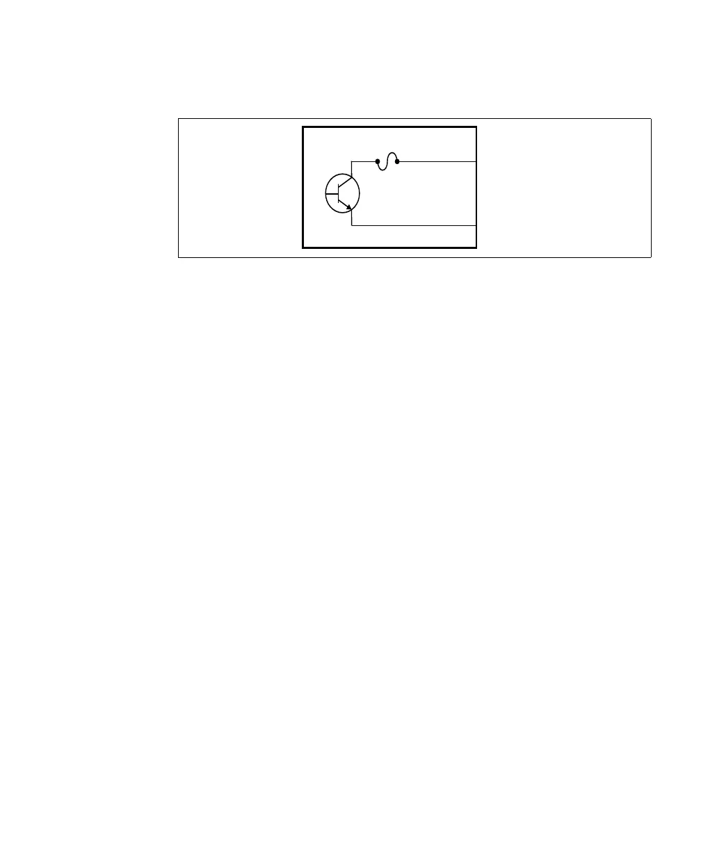
The diagram below depicts Matrox Iris GTR’s on-board fuse.
Optically-isolated
output signals
The Matrox Iris GTR auxiliary output signals are optically isolated from the power
and analog intensity (dimming) control signal as well as from the Matrox Iris GTR
auxiliary input signals. They are not, however, optically isolated from each other
as they share a common pin (AUX_OUT_COMMON).
About the
connections in the
following
subsections
The following subsections detail how to connect the most common third-party
devices to the Matrox Iris GTR auxiliary output signals. Ground is only shown
in the following subsections for reference, in case you need to reference your return
path to ground. To connect to a light controller (such as, an Advanced
Illumination or Smart Vision Lights lighting controller), see Connecting a light
controller and the analog intensity control signal section later in this chapter.
Power, as depicted in the following diagrams, represents a nominal voltage of up
to 24 V (+/- 10%). For minimum and maximum voltage requirements, refer to
the electrical specification of the opto-isolated output signals, in
Appendix B: Technical reference.
The signal names in this section are shortened to fit within the diagrams: from
M_AUX_OPTOIND_OUTn to AUX_OUT and from
M_AUX_OPTOIND_OUT_COMMON to AUX_OUT_COMMON.
Equivalent circuit only
fuse
max.
50 mA
aux_out
aux_out_common