72 Appendix B: Technical reference
The pinout for the VGA/USB connector is as follows:
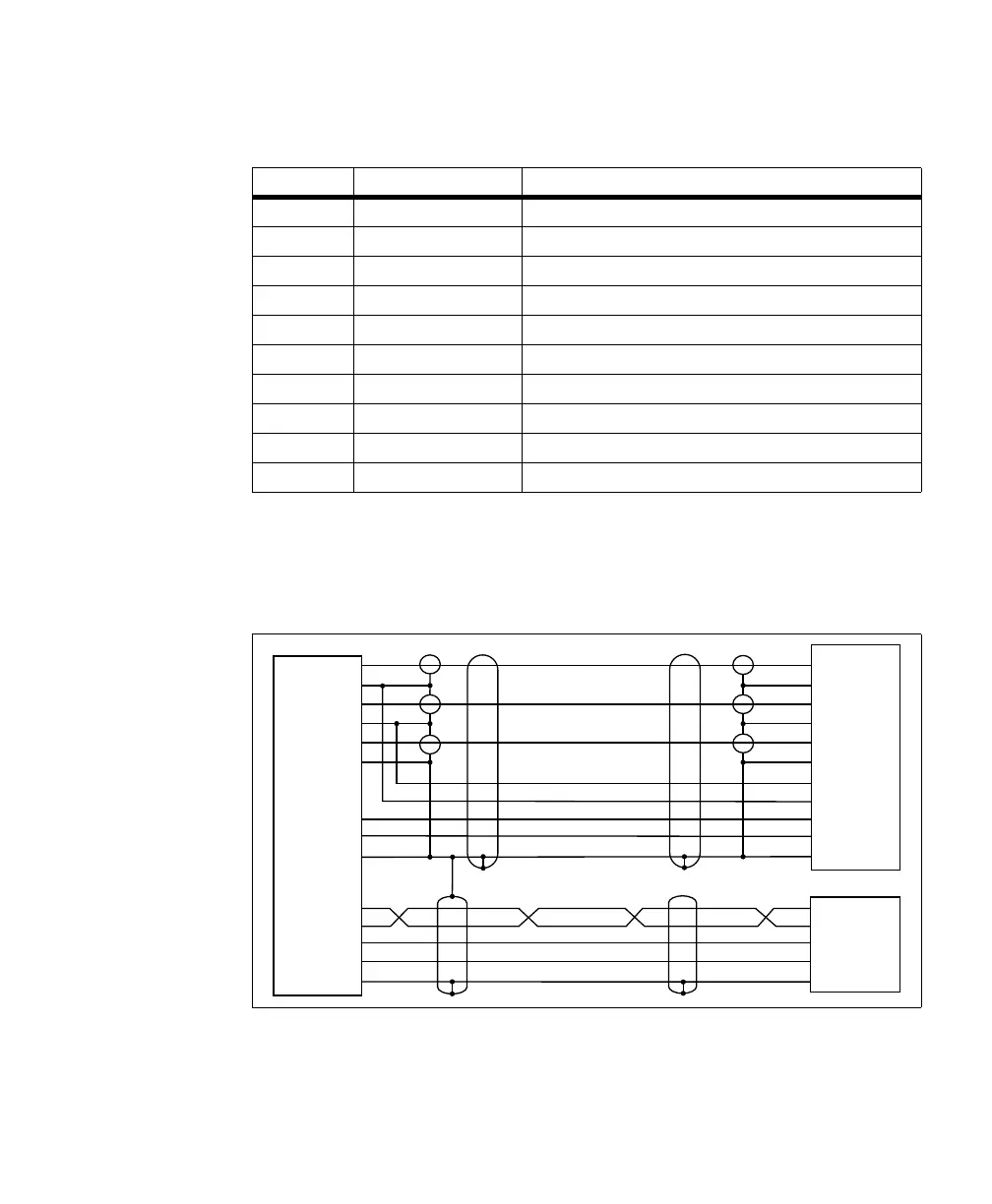
The following is a wire-diagram of the Matrox GTR-CBL-VGAUSB cable,
showing the connection between the Matrox Iris GTR VGA/USB connector on
one end and the HD-15 and USB connectors on the other.
This cable can be purchased as part of the starter kit, or separately from Matrox
(GTR-CBL-VGAUSB).
Pin number Signal name Description
1 USB PWR 5 V supplied from your Matrox Iris GTR to the USB peripherals.
2 USB_DATA_P USB data +.
3 USB_DATA_N USB data -.
10 USB_REF USB reference.
5 RED_VID_OUT R component of the RGB video output signal.
6 BLUE_VID_OUT B component of the RGB video output signal.
7 VSYNC Vertical sync of the RGB video output signal.
8 HSYNC Horizontal sync of the RGB video output signal.
9 GREEN_VID_OUT G component of the RGB video output signal.
4, 11, 12 VGA _REF VGA reference.
RED
GREEN
BLUE
VGA Reference
VGA Reference
HS
VS
DRAIN WIRE
USB DATA
USB DATA#
USB VCC
USB Reference
DRAIN WIRE
9
GND 4
GND 12
6 GND
GND 11
7 GND
8 GND
2
3
1
10
5
M12 PHOENIX CONTACT
1
6
2
7
3
8
5
10
13
14
SHELL
1
2
3
4
SHELL
USB FEMALE
HD-15 FEMALE
SHELL
SHELL