Operating Instructions – Labmaster
©
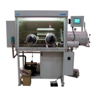
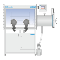
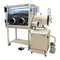
130 and MB20G Systems
Instruction Manual
Chapter 5: System Screens
© MBraun, Inc. Edition 1/2007 Page 5-1
CHAPTER 5: SYSTEM SCREENS
5.1 General Information
The system is operated using a Touch Screen located on the side of the system above the
antechamber. This chapter provides an introduction to the various screens that the user will
access during operation of the system.
To activate a component or operation touch the corresponding button. To deactivate a
component or operation touch the corresponding button again.
Red buttons and icons represent inactive functions, green buttons and icons represent active
functions and gray buttons represent functions which are nonexistent or temporarily unavailable.
The purifier icon will also be displayed in yellow signaling the regeneration process is active.
The list below displays the buttons and information fields which are located on multiple screens
associated with the system.
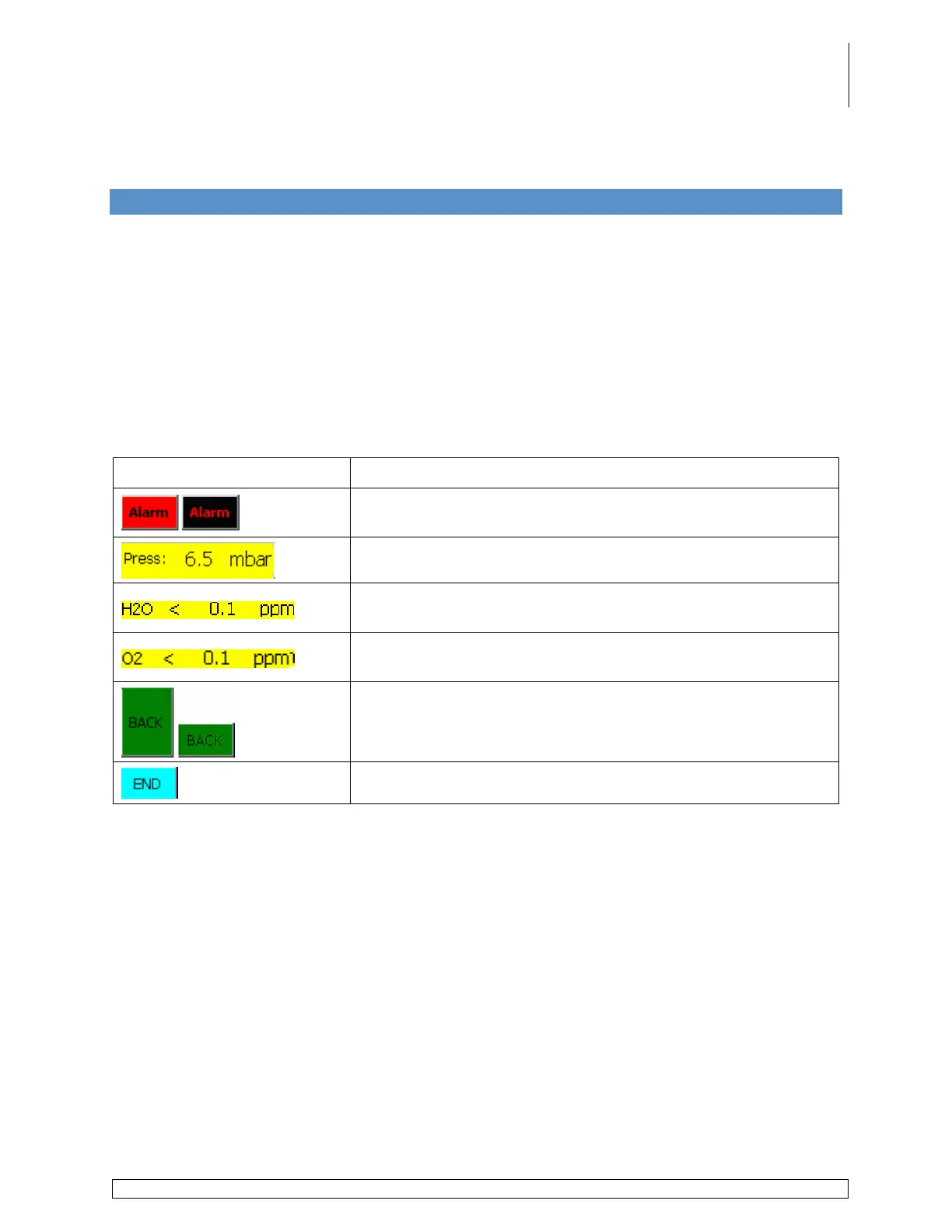
Button / Information Field Description
Displays the Alarm Screen. Blinks black & red when an alarm
is present.
Displays the actual glovebox pressure.
Displays the moisture level inside the glovebox as detected by
the analyzer.
Displays the oxygen level inside the glovebox as detected by
the analyzer.
Displays the previous screen.
Displays the Start screen.