Operating Instructions – Labmaster
©
130 and MB20G Systems
Instruction Manual
Chapter 7: Installation
© MBraun, Inc. Edition 1/2007 Page 7-3
7.3 Assembling the Glovebox
General Information
A packing checklist has been included with the system. Most components included on this
checklist have been packed in the antechamber. Prior to beginning the installation process,
unpack, unwrap and identify each component and ensure the appropriate number of items has
been included with the shipment as indicated on this checklist. Contact the M.Braun Service
Department if any of the items are missing or damaged.
Place all components in an easily accessible location close to the glovebox in an organized
manner to ease in the assembly process.
This chapter contains assembly information for the Labmaster
©
130 (stand mounted purifier)
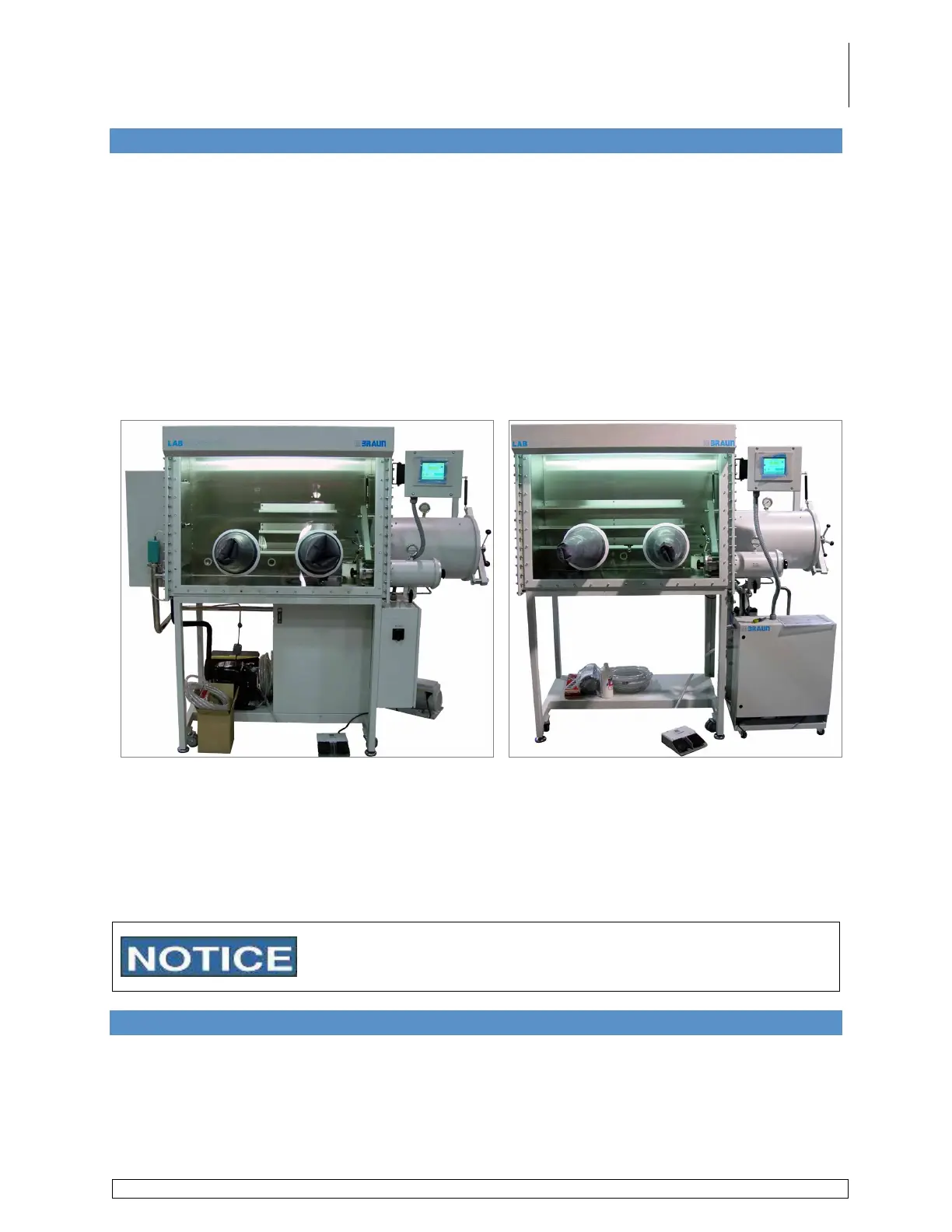
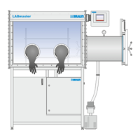
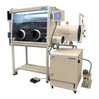
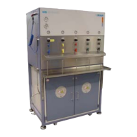
and MB20G (stand-alone) style gloveboxes. Please refer to the pictures below to determine the
type of system and follow the corresponding assembly instructions.
Figure 2 - Stand Mounted Purifier Figure 3 - Stand-Alone Purifier
Section 7.6 provides instructions for installing a Stand Mounted purifier glovebox system.
Section 7.7 provides instructions for installing Stand-Alone purifier glovebox systems. Sections
7.4-7.5 and 7.8 through 7.13 provide instructions which pertain to both types of glovebox
systems.
Prior to beginning the installation process move the system into the permanent location but
allow enough clearance during the installation process to work behind the box and/or purifier.
These installation instructions include all possible components for a
glovebox system. Please note, not all components are included
with every system.
7.4 Connecting the Antechamber Gauges and Sensors
The gauges and sensors depicted below will depend on the options purchased with the system.
Please refer to your Project Checklist for more information.
The gauges are attached with KF16 clamps and o-rings and the electrical connections are made
by attaching the corresponding labeled plug from the system to the gauge and/or sensor. The
picture below provides information for the various gauges and the completed assembly.