98 MDS iNET 900 User’s Guide MDS 05-2806A01, Rev. A
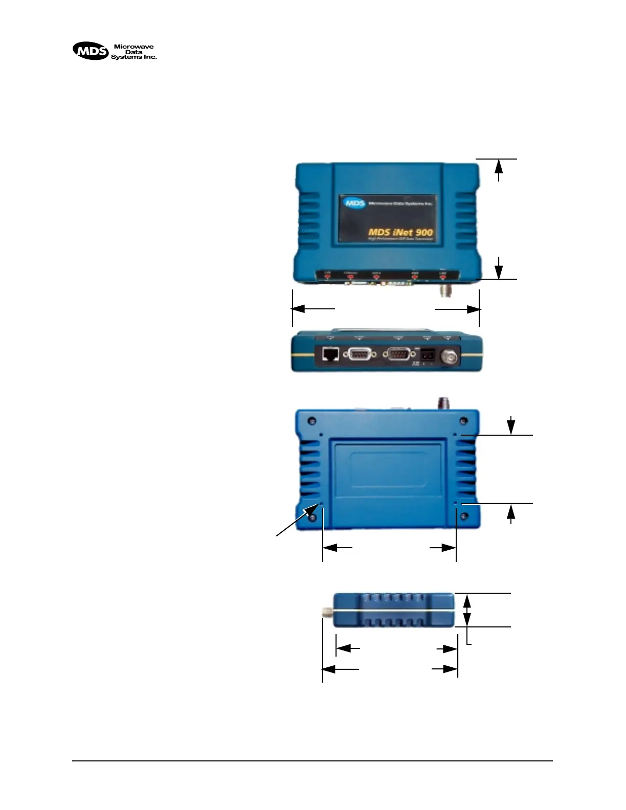
Unit Dimensions
Figure 5-2 shows the dimensions of the iNET case and its mounting
holes. If possible, choose a mounting location that provides easy access
to the connectors on the end of the radio and an unobstructed view of the
LED status indicators.
Figure 5-2. MDS iNET 900 Dimensions
4.25˝ (10.8 cm)
4.75˝ (12 cm)
1.25˝ (3.17 cm)
6.75˝ (17.15 cm)
4.5˝ (11.4 cm)
TOP
FRONT
SIDE
BOTTOM
2.5˝ (6.35 cm)
4.85˝ (12/3 cm)
THREADED HOLES
FOR MOUNTING
SCREWS (4)
#6-32 X 1/4˝
Not to scale