TA80V User Manual
2.3. Vaporizer Control
If the anesthesia machine is equipped with a vaporizer provided by the manufacturer or intends to
install a recommended vaporizer according to its instructions, the following instructions are required
1. There are detailed description of the anesthesia vaporizer performance, including the
environmental humidity, environmental pressure, tilt, input flow rate to 8 L/min or the manufacturer's
set range (the larger value of the two) and the influence of changes in the gas mixture composition.
2. When the anesthesia machine, and an anesthesia vaporizer not match, their performance
decreases
3. Detecting the carrier gas recommended anesthesia vaporizer, and a gas flow rate of gas
analysis, if the machine is recommended to use some kind of anesthesia ventilator, to be detected on
the anesthesia vaporizer, the ventilator setting conditions.
4. If the anesthesia vaporizer cannot be calibrated within the first scale range on "OFF" and "0",
the anesthesia vaporizer cannot and should not use this range.
5. The volume of the anesthetic agent in the anesthesia vaporizer from the lowest level to the
highest level.
For more detailed information about the anesthesia vaporizer, please refer to the anesthesia
vaporizer operation and maintenance manual
NOTE The vaporizer used with the TA80V anesthesia system shall comply with ISO 8835-4.
2.4. Anesthesia Ventilator Control
NOTE Anesthesia ventilator meets the requirements of ISO 8835-5
NOTE The conditions for monitoring respiratory parameters in this system: environmental
temperature: 29°C, gas temperature: 30°C, air humidity: 30%, gas: oxygen
NOTE If the temperature of the sensor is lower than or equal to the dew point temperature of
the breathing gas, water vapor may condense on the surface of the sensor. In this
way, the displayed value of O2 concentration in the loop may be lower than the actual
value.
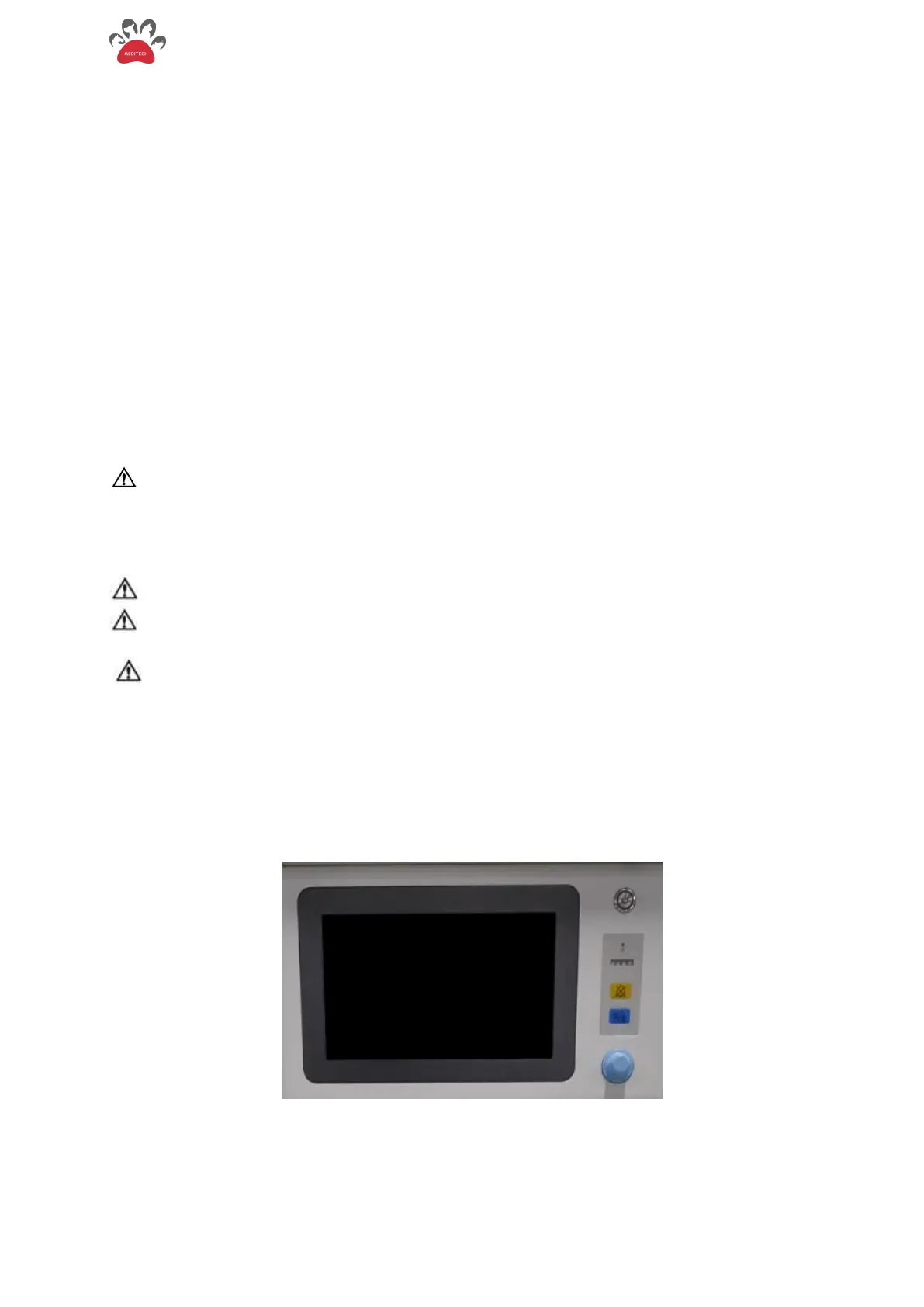
2.4.1. Front Panel of the Anesthesia Ventilator
The front panel consists of touch screen, function keys, indicator lights and knobs, as shown in
Figure 2-6.
Figure 2-6 The front panel of the anesthesia ventilator