44 Operator's Manual English
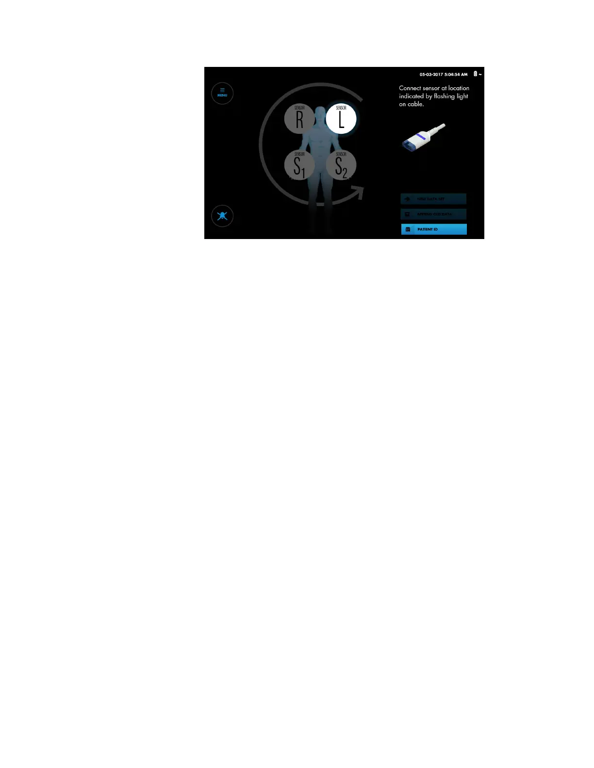
Figure 23. Set-Up Screen - Prompt for Sensor Connection
4. Optionally, you can set the sensor sequence for the number of sensors you are
using. If you are using fewer than four sensors, you can set the number to three or
two for onscreen representations. See Changing the Sensor Placement Sequence,
page 46.
5. Connect the RSCs to the sensors that have been applied to the patient:
Caution: If two sensors are placed in close proximity to each other on a patient, the
same preamplifier should be connected to both sensors to avoid poor
performance.
a. Note the highlighted sensor location on screen (Figure 23). Locate the
corresponding sensor applied to the patient.
b. Look for the flashing blue light on the preamplifier and at the end of the
corresponding RSC.
c. Align the sensor’s male connector with the connection slot on the RSC. The
connector and slot are keyed to guide insertion.
d. Press firmly until the connector snaps into place. The monitoring system
indicates proper connection by displaying an rSO
2
reading at the
corresponding sensor location. If the sensor was previously used on the
monitoring system, the last baseline obtained on the sensor is also displayed.
e. Look for the next highlighted sensor location on screen and the next flashing
blue light on the preamplifier and RSC. Connect the next sensor to the
corresponding RSC.
f. Repeat these steps for each sensor applied to the patient.
g. Verify the placement of all sensors by briefly pressing each on-screen sensor
location and noting the blue flashing light on the RSC cable. Make sure that the
onscreen location matches the sensor location on the patient. If the location
does not match, you can reposition the on-screen sensors rather than
disconnecting the RSCs. See Repositioning On-Screen Sensors, page 47.
Note: As you connect the RSCs to sensors applied to the patient, readings are
displayed on the Set-up screen. However, trends are not tracked and physiological
alarms are disabled. Do not attempt to monitor the patient from the Set-up screen.
6. Check the location of all cables connected to the monitoring system. Make sure
that the patient is not lying on any cables or connectors. To prevent entanglement
and prolonged contact with patient skin, you can secure the RSCs with the strain-
 Loading...