5
Operator's Manual English 79
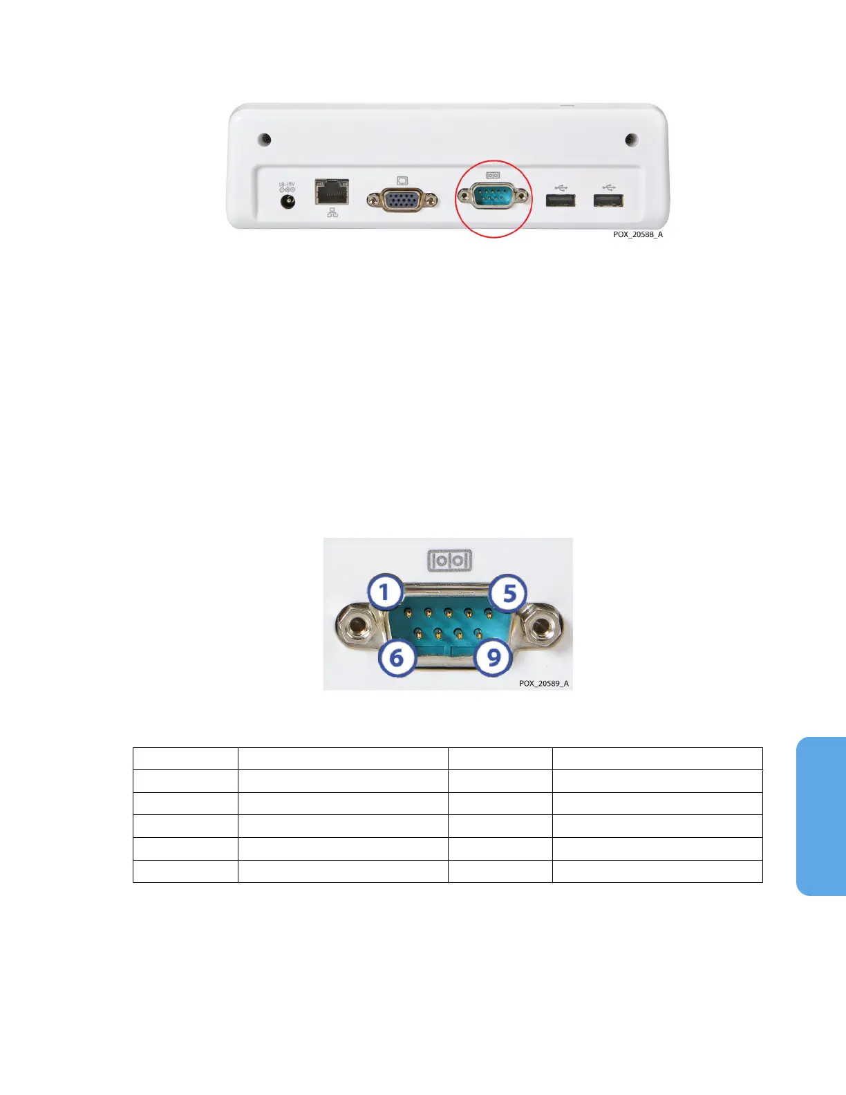
Figure 67. Serial Port on Docking Station
5.5.1. Serial Port Specifications
The monitoring system’s serial port uses the following protocol:
•
Baud: 19200 for VUE LINK format; 9600 for PC LINK 1 and PC LINK 2 formats
•
No parity
•
8 data bits
•
1 stop bit
•
Flow control: hardware
Pin-outs for the serial port are shown in Figure 68 and described in Table 12.
Figure 68. Serial Port Pin-Outs
Table 12. Serial Port Pin-Out Descriptions
Pin # Signal name Pin # Signal name
1 Data carrier detect 6 Data set ready
2 Receive data 7 Request to send
3 Transmit data 8 Clear to send
4 Data terminal ready 9 Ring indicator
5 Ground
5.5.2. Transmitting Real-Time Data to a Philips IntelliBridge™* and
VueLink™* Open Interface (IVOI) Module
Warning: An external multi-parameter system will not generate an alarm or error message
if remote communication between the multi-parameter system and the monitoring system
has been broken. During this period of no remote communication, the monitoring system
will continue to monitor, generate alarms, and display status messages. The multi-
 Loading...