HARDWARE MANUAL Document reference MAMPS-HW/E
VM600 machinery protection system (MPS) Edition 18 - March 2022
3-10
VM600 6U 19" rack backplane (ABE04x)
GENERAL SYSTEM DESCRIPTION
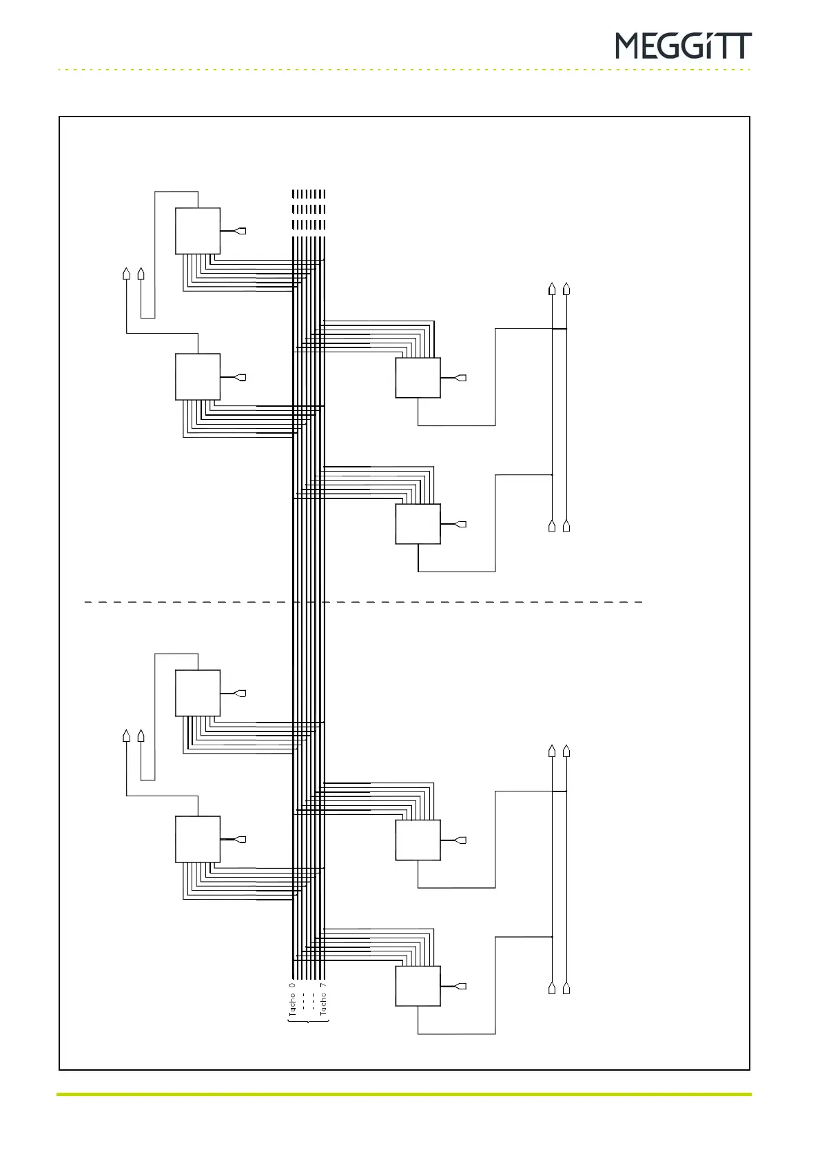
Figure 3-5: Schematic of the Tacho Bus
IOC #A IOC #B
Notes
1. Software generated control signal to inhibit the (de)multiplexer or select the appropriate line.
Tacho Bus lines 1 to 6 are available for speed/tacho signal sharing. Tacho Bus lines 7 and 8 are reserved for cold-junction compensation (CJC).
Control signal
(see note 1)
Control signal
(see note 1)
Control signal
(see note 1)
Control signal
(see note 1)
Control signal
(see note 1)
Control signal
(see note 1)
Control signal
(see note 1)
Control signal
(see note 1)
Demulti
-plexer
Demulti
-plexer
Demulti
-plexer
Demulti
-plexer
Multi-
plexer
Multi-
plexer
Multi-
plexer
Multi-
plexer
TACHO BUS
To MPC #A
To MPC #B
To MPC #A To MPC #BFrom IOC #A From IOC #B
SPEED 1A “REMOTE”
SPEED 2A “REMOTE”
SPEED 1B “REMOTE”
SPEED 2B “REMOTE”
SPEED 1B “LOCAL”
SPEED 2B “LOCAL”
SPEED 1A “LOCAL”
SPEED 2A “LOCAL”
SPEED 1A
SPEED 2A
SPEED 1B
SPEED 2B
 Loading...
