HARDWARE MANUAL Document reference MAMPS-HW/E
VM600 machinery protection system (MPS) Edition 18 - March 2022
3-6
VM600 6U 19" rack backplane (ABE04x)
GENERAL SYSTEM DESCRIPTION
3.4 VM600 6U 19" rack backplane (ABE04x)
3.4.1 General overview
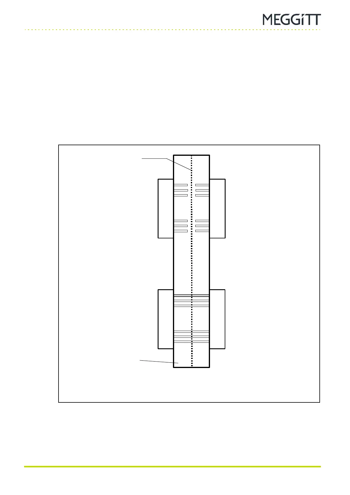
The VM600 MPS using a 6U 19" system rack (ABE04x) with a custom-designed backplane
combines features of a VME backplane and other special features to support the Meggitt
vibro-meter
®
product line (see Figure 3-3 and Figure 3-4).
This backplane consists of 3 different systems:
• A VME bus (P1)
• An analog bus (P3)
• Through connections between P2 and P4.
P1 P3
P2 P4
...
...
...
...
...
...
...
...
...
...
...
...
Shield
Backplane
Front card cage
of VM600 rack
(Female connectors)
Rear card cage
of VM600 rack
(Male connectors)
Figure 3-3: Cross-section of a VM600 rack (ABE04x) backplane
showing the four buses and connectors

 Loading...