Document reference MAMPS-HW/E HARDWARE MANUAL
Edition 18 - March 2022 VM600 machinery protection system (MPS)
2-27
RPS6U rack power supply (ABE04x only)
OVERVIEW OF VM600 MPS HARDWARE
2.10.8 Front panels
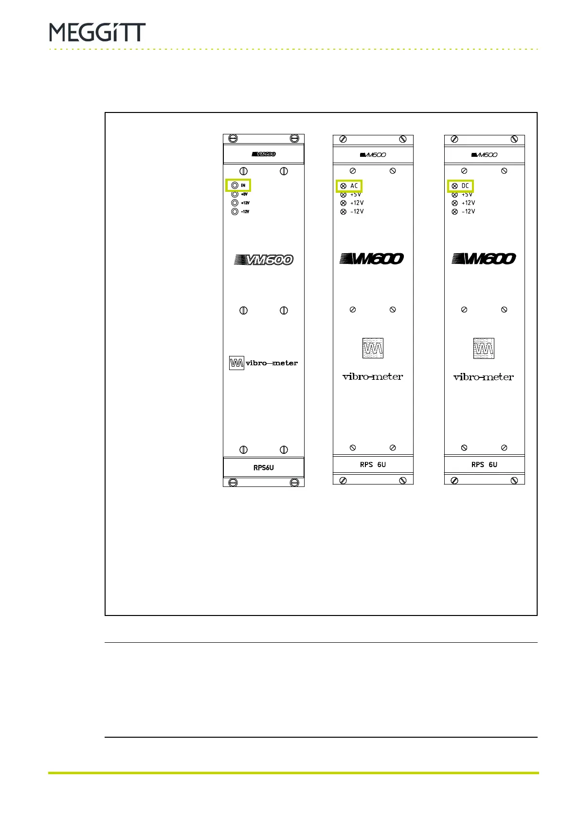
Figure 2-16 shows the panels of RPS6U rack power supplies with different inputs: AC or DC.
NOTE: For a VM600 rack with two RPS6U rack power supplies connected to two external
mains supplies (see 2.10.7 VM600 racks and power supply redundancy), if one of
the external mains supplies is not connected/operating, the +5V LED on the
RPS6U connected to that (non-operating) external mains supply can still show
yellow even though that particular RPS6U’s +5 V output is not operating normally.
(This incorrect 5V LED indication is due to reverse/leakage current across an
ORing diode used to connect the +5 V outputs from both RPS6Us.)
Figure 2-16: Front panels for the different versions of the RPS6U rack power supply
(a) Panel of later (higher-power)
version of the RPS6U rack
power supply
(b) Panels of earlier (original)
version of the RPS6U rack power supply:
AC-input version (left) and
DC-input version (right)
IN, AC or DC LED:
Green indicates that the
external mains supply is
present and is within the
normal range.
This LED is on when
the RPS6U is operating
normally.
+5V, +12V and −12V LEDs:
Yellow indicates that the
corresponding internal
supply voltage is being
generated and is within the
normal range.
These LEDs are on when
the RPS6U is operating
normally.
(AC-input version) (DC-input version)
 Loading...
