HARDWARE MANUAL Document reference MAMPS-HW/E
VM600 machinery protection system (MPS) Edition 18 - March 2022
7-22
Shaft relative expansion
PROCESSING MODES AND APPLICATIONS
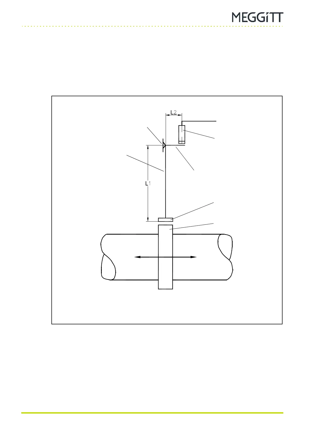
7.9.4 Pendulum method
(1) Description
With this configuration a magnet on a lever arm is used to follow the movement of the shaft
collar (see Figure 7-17). The lever arm ratio (L1 / L2) enables the measuring range to be
extended well beyond that of a transducer used on its own.
ΔL = GAP
− GAP
i
where GAPi is the initial gap.
Figure 7-17: A measuring system using a pendulum with magnetic
head installed near a shaft collar
Proximity transducer
Short arm of lever
Shaft collar
Head of pendulum
(magnetic)
Vertical arm of pendulum
(long arm of lever)
Shaft
Pivot point
 Loading...
