Document reference MAMPS-HW/E HARDWARE MANUAL
Edition 18 - March 2022 VM600 machinery protection system (MPS)
7-11
Position measurement
PROCESSING MODES AND APPLICATIONS
Similarly, if the sensors are installed and measure in opposite directions or one has a
reversed polarity ( ), then:
• AS = BBAB − RS (that is, the signals must be subtracted).
• So in the Absolute shaft vibration (AS) processing function, the angle between the two
sensors must be configured as 180°.
It is worth noting that the original BBAB and RS outputs (values and alarms) are also
available from their respective single-channel processing functions (see Figure 7-6) for use
by the machinery monitoring system.
NOTE: It should be remembered that when a signal is integrated, the output signal lags
the input signal by 90° (that is, the output signal is 90° behind the input signal). This
is automatically considered by any digital integration performed by an MPC4 card.
7.6 Position measurement
(1) Description
The relative position of a shaft can be measured by placing a proximity probe on the bearing.
This type of measurement is particularly applicable to fluid-film thrust bearings where it is
necessary to measure the axial motion of the shaft relative to the bearing.
The following front-end components are the most commonly used:
• TQxxx proximity transducer + IQSxxx signal conditioner
• TQxxx proximity transducer + IQSxxx signal conditioner + (Intrinsically safe) GSVxxx
power supply and safety barrier (applications).
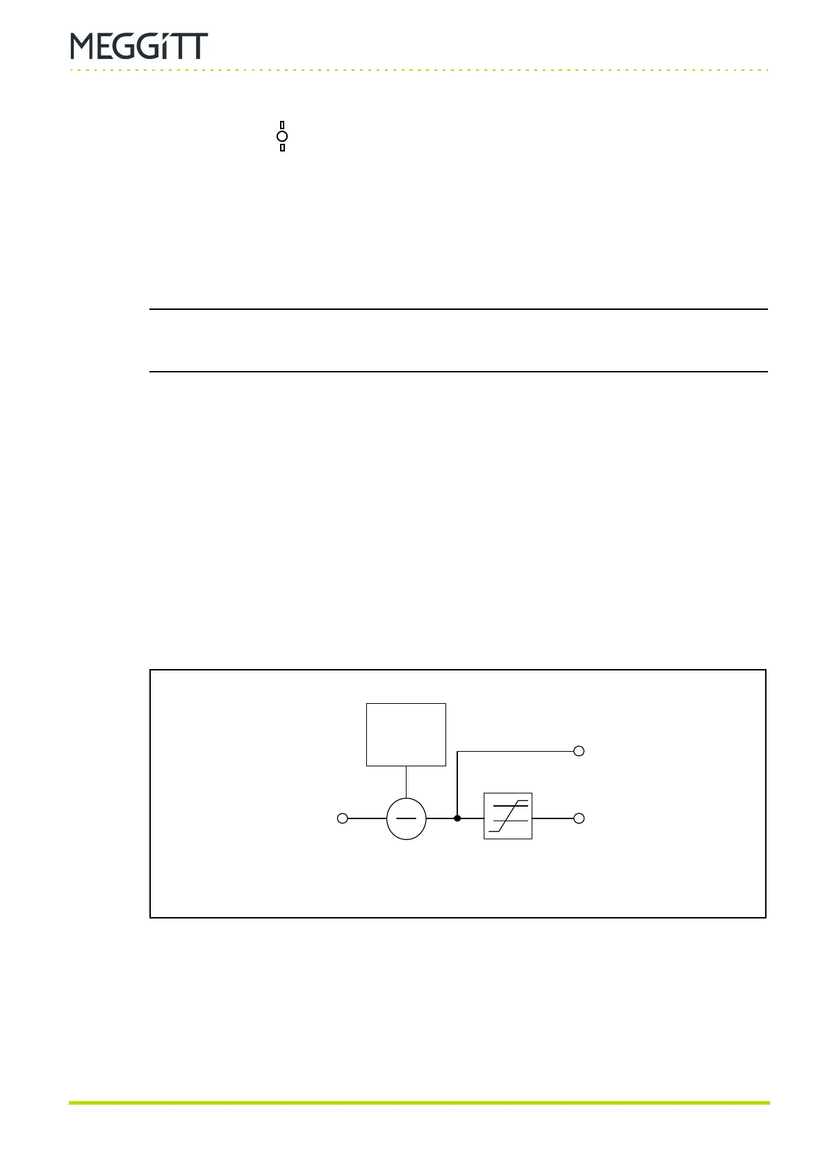
(2) Block diagram
With a proximity probe connected to the MPS, the position processing function calculates the
position of the target relative to a reference point.
The initial target position (gap) must be stored (or configured). This will be used as a
reference position for measurement purposes. This value ( X
initial
) depends on the physical
probe placement, and must be subtracted from the measured value ( X
in
) in order to give
the target position relative to the reference position:
X
out
= X
in
− X
initial
Figure 7-7: Block diagram showing position processing
Position value
( X
out
)
Alarms
Position input
( X
in
)
Initial gap
(X
initial
)
 Loading...
