HARDWARE MANUAL Document reference MAMPS-HW/E
VM600 machinery protection system (MPS) Edition 18 - March 2022
2-10
MPC4 machinery protection card (ABE04x and ABE056)
OVERVIEW OF VM600 MPS HARDWARE
2.2 MPC4 machinery protection card (ABE04x and ABE056)
The MPC4 card has the following panel elements (see Figure 2-8):
1- One global DIAG/STATUS indicator for the MPC4
/ IOC4T card pair
This multi-coloured, multi-function LED is used to indicate:
• The status of the card configuration
• Whether special functions such as Trip Multiply (TM) or Danger Bypass (DB) are
in use
• An MPC4 card failure due to a hardware or a software problem.
2- BNC connectors RAW OUT 1 to RAW OUT 4
A connector is present for each of the four measurement channels. Used to output raw
analog signals (corresponding to, for example, vibration or dynamic pressure).
3- BNC connectors TACHO OUT 1 and TACHO OUT 2
A connector is present for each of the two rotational speed channels. Used to output
speed/phase reference signals. These signals are TTL-conditioned.
4- Status indicators for the four measurement channels and the 2 rotational speed channels
Each multi-coloured, multi-function LED is used to indicate:
• Whether the signal input for that channel is valid
• The presence of an incoming signal in the Alert/Danger condition
• Whether the channel inhibit function is in use.
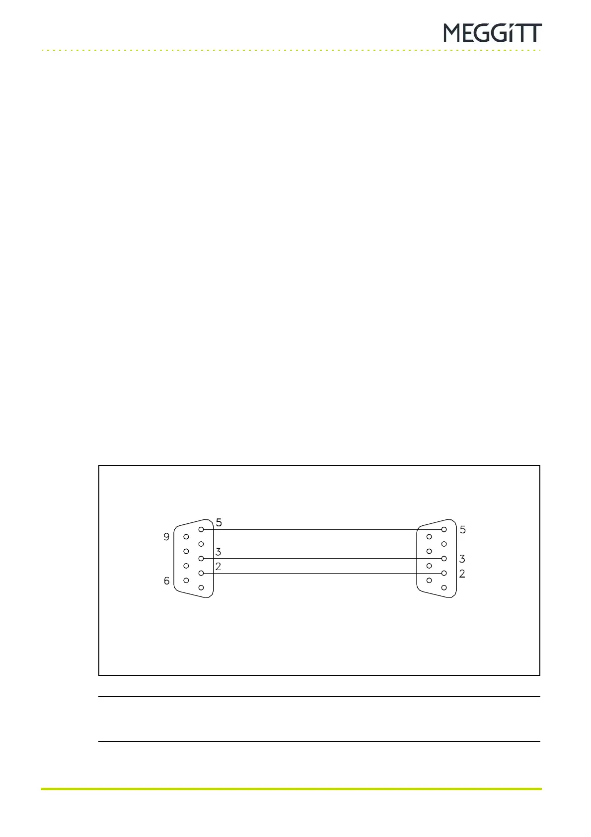
5- RS-232 connector
This 9-pin D-sub connector can be used to configure an MPC4 card in a stand-alone
rack. This is done via an interface cable from a computer running one of the VM600
MPSx software packages (MPS1 or MPS2). See Figure 2-7 for details of the interface
cable.
NOTE: The MPC4 machinery protection card is available in different versions, including a
standard version, a separate circuits version and a safety (SIL) version.
See 4 MPC4 / IOC4T card pair for additional information.
Figure 2-7: Interface cable used to connect the MPC4 (or AMC8) card to the
serial port of a computer running the configuration software
Connect to
MPC4 (or AMC8) card
Male
connector
Female
connector
Connect to
computer

 Loading...