HARDWARE MANUAL Document reference MAMPS-HW/E
VM600 machinery protection system (MPS) Edition 18 - March 2022
7-20
Shaft relative expansion
PROCESSING MODES AND APPLICATIONS
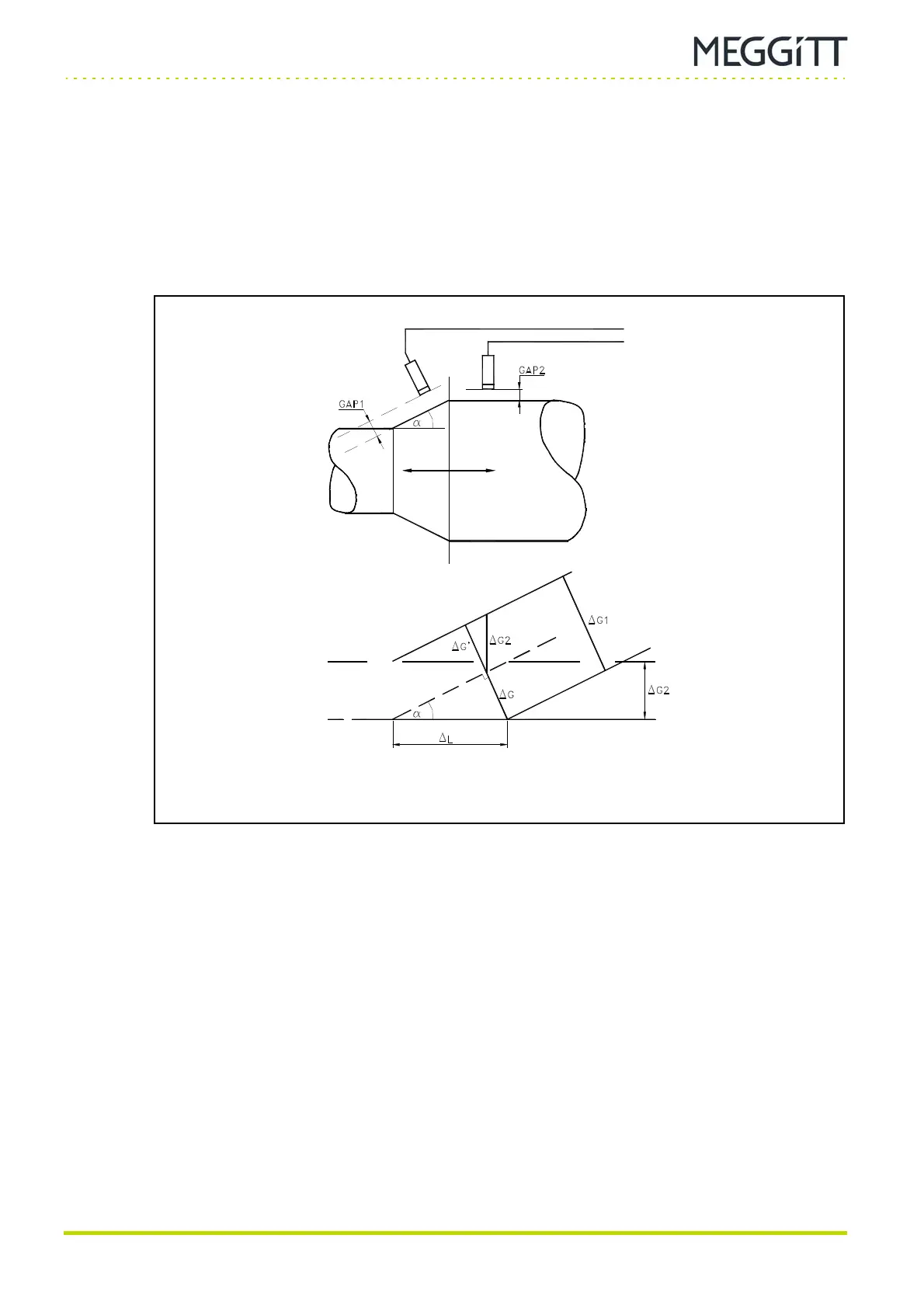
7.9.3 Single shaft taper method
(1) Description
Two probes are used in this configuration (see Figure 7-15). The first probe is placed
perpendicularly to a single shaft taper and measures expansion. The second probe is placed
perpendicularly to the axis of rotation to compensate for any radial motion of the shaft which
could introduce an error in the measured expansion value. Both probes operate within their
measuring range at the same time.
For this configuration the following formulae apply:
ΔL = ΔG / sinα
ΔG = ΔG1
− ΔG’
ΔG’ = ΔG2 cosα
=> ΔL = (ΔG1
− ΔG2 cosα) / sinα
finally,
ΔL = [ (GAP1
− GAP1
i
) − (GAP2 − GAP2
i
) cosα ] / sinα
where GAP
i
is the initial gap value.
Figure 7-15: Two proximity probes mounted near a shaft fitted with a single taper
 Loading...
