HARDWARE MANUAL Document reference MAMPS-HW/E
VM600 machinery protection system (MPS) Edition 18 - March 2022
13 - 18
Location of components on the CPUM card (earlier MSM586EN version)
CONFIGURATION OF CPUM / IOCN CARDS
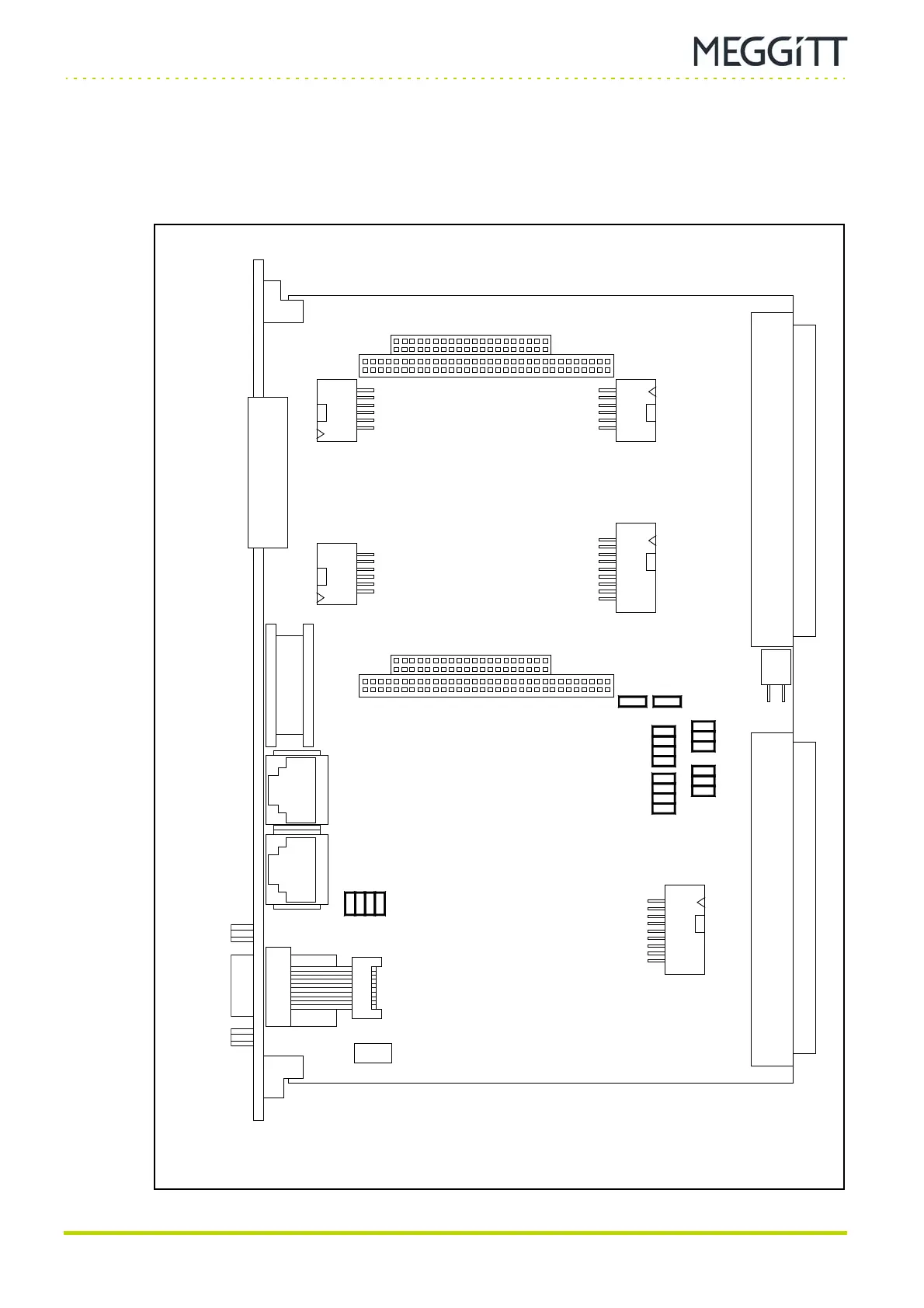
13.8Location of components on the CPUM card (earlier MSM586EN version)
Figure 13-17 shows the position of jumpers and large components on earlier versions of the
CPUM card (PNR 200-595-075-HHh or earlier) designed to be fitted with the MSM586EN or
equivalent CPU module (see 6.1 Different versions of the CPUM card).
Figure 13-17: Location of jumpers on the CPUM card (earlier MSM586EN version)
J2
(P2)
J1
(P1)
J13
J11
J12
J10
J18
J21J17
J16
J20
J28 J29
J3
J15 J14
J47
J48
J30
J19
J4 J5
J34
J33
J32
J31
J38
J37
J36
J35
J43
J45
J41
J44
J46
J39
J53
J52
J40
J42
Q3
CPUM
panel
RS-232
NET

 Loading...