Document reference MAMPS-HW/E HARDWARE MANUAL
Edition 18 - March 2022 VM600 machinery protection system (MPS)
9-41
Using the Raw Bus to share measurement channel inputs
CONFIGURATION OF MPC4 / IOC4T CARDS
9.11Using the Raw Bus to share measurement channel inputs
The Raw Bus consists of 64 parallel bus lines, arranged as 32 differential line pairs. It allows
the raw analog signals coming from measurement transducers and devices connected to the
dynamic signal inputs of an IOC4T card (via the CH1, CH2, CH3 and CH4, accessible at the
rear of the ABE04x rack) to be placed on a Raw bus line pair. The dynamic signal input
(measurement channel) is subsequently available throughout the VM600 rack to be used as
an input by any other IOC card in the rack.
This feature is typically used to reduce external wiring requirements. For example, in a
VM600 rack featuring both MPS and CMS hardware, signals wired to the MPS cards
(externally) can be shared with the CMS cards over the Raw bus (internally).
The allocation of a specific Raw Bus line pair to a measurement channel is done by setting
jumpers on the IOC4T card (and on the IOC16T card – refer to the VM600 condition
monitoring system (CMS) hardware manual (MACMS-HW/E)). The mapping of the
measurement channels to the Raw Bus line pairs is summarised in Table 9-6, together with
the required jumper settings. The position of the relevant jumpers on the IOC4T card is shown
in Figure 9-29 with an explanation of which jumpers correspond to which Raw Bus lines
(see “measurement channel selection” on the right of the figure).
For information on the allocation of a specific Raw Bus line pair to a control signal line, see
9.12.2 Using the Raw Bus to switch relays.
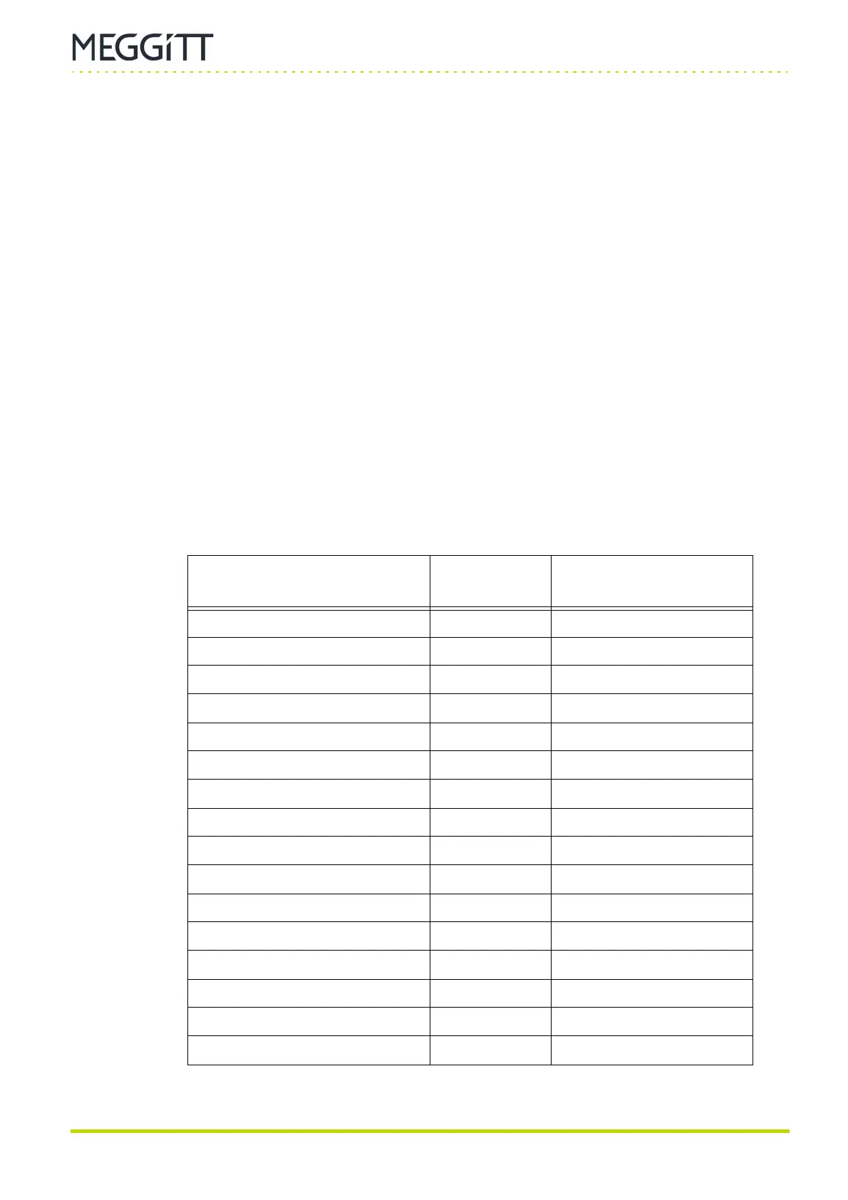
Table 9-6: Raw bus lines and jumpers associated with measurement channels
for the MPC4 card
MPC4 measurement channel
(raw analog signal)
Raw Bus
line pair
IOC4T jumper settings
(contacts 1-3 closed)
Measurement channel 1 0 J300 and J301
Measurement channel 2 1 J302 and J303
Measurement channel 3 2 J304 and J305
Measurement channel 4 3 J306 and J307
Measurement channel 1 4 J308 and J309
Measurement channel 2 5 J310 and J311
Measurement channel 3 6 J312 and J313
Measurement channel 4 7 J314 and J315
Measurement channel 1 8 J316 and J317
Measurement channel 2 9 J318 and J319
Measurement channel 3 10 J320 and J321
Measurement channel 4 11 J322 and J323
Measurement channel 1 12 J324 and J325
Measurement channel 2 13 J326 and J327
Measurement channel 3 14 J328 and J329
Measurement channel 4 15 J330 and J331

 Loading...