Document reference MAMPS-HW/E HARDWARE MANUAL
Edition 18 - March 2022 VM600 machinery protection system (MPS)
9-43
Using the Raw Bus to share measurement channel inputs
CONFIGURATION OF MPC4 / IOC4T CARDS
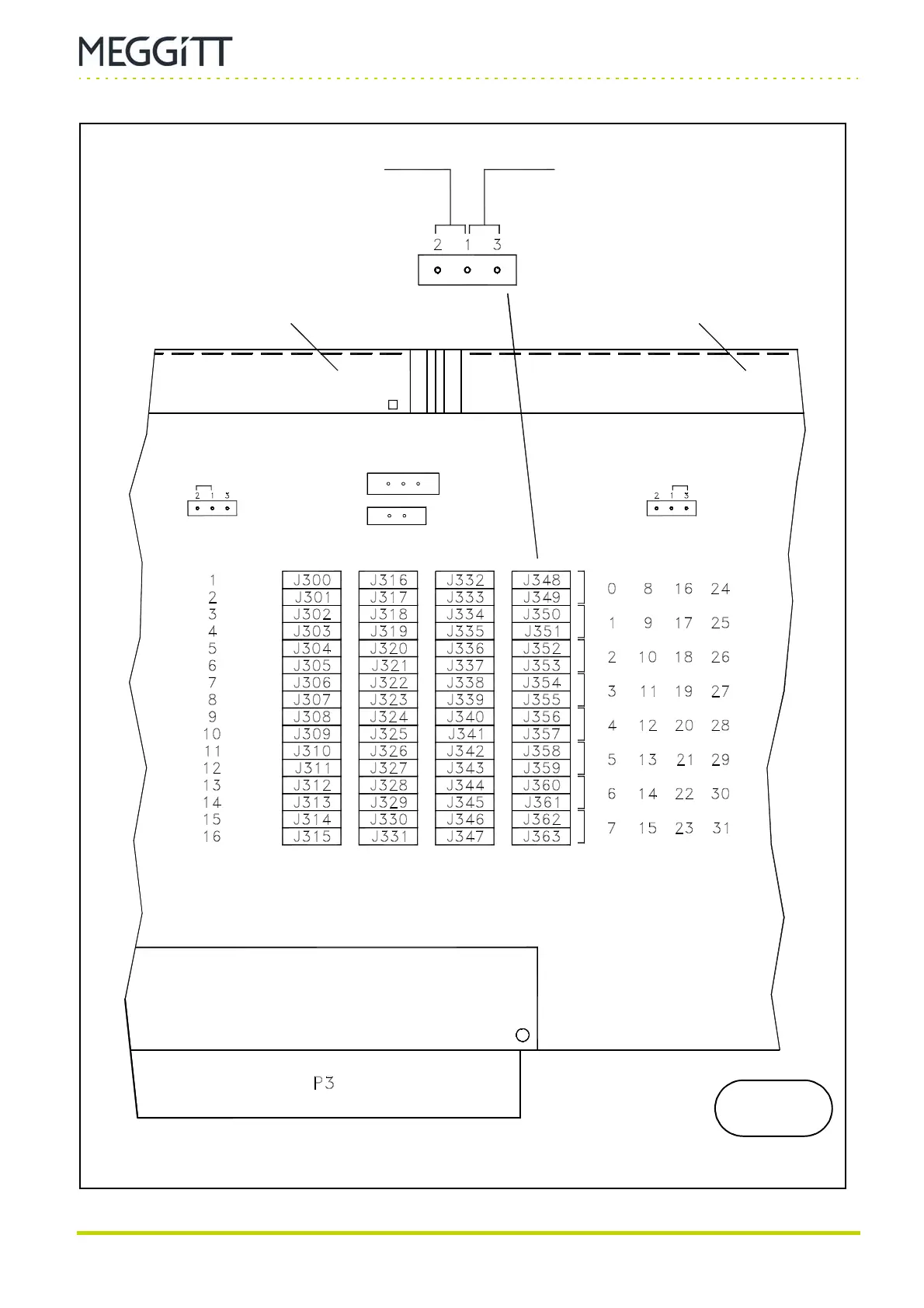
Figure 9-29: Position of jumpers related to the Raw Bus on the IOC4T card
(Top of card)
(Bottom of card)
Connector J2Connector J1
Measurement channel
selection
Relay
selection
Contacts 1-2 closed:
Jumper settings to allocate a
Raw Bus line pair to a
specific relay
IOC4T
This number matrix gives
the Raw Bus line pairs
corresponding to the jumper
matrix on the left.
Contacts 1-3 closed:
Jumper settings to allocate a
Raw Bus line pair to a
specific raw analog signal
(measurement channel)
Relay selection Measurement channel selection
J1016
213
J1015
(Case ground)
(VME ground)
 Loading...
