Document reference MAMPS-HW/E HARDWARE MANUAL
Edition 18 - March 2022 VM600 machinery protection system (MPS)
13 - 15
Connectors on the IOCN card
CONFIGURATION OF CPUM / IOCN CARDS
13.6Connectors on the IOCN card
NOTE: The pin definitions shown in Figure 13-14 and Figure 13-15 are for the connectors
(female) on the IOCN card’s panel, such as the 8P8C (RJ45) and the
6P6C (RJ12/RJ25).
13.6.1 Modular connector pinouts
For modular connectors such as 6P6C (RJ12/RJ25) or 8P8C (RJ45) used by the IOCN card
(and MPC4 card), the pin definitions of the connectors (male) on the cables that will mate with
the connectors (female) on an IOCN card are established as follows:
1- Hold the cable connector (male) in your hand with the tab side down and with the cable
opening facing towards you.
2- Reading from left to right, the pins are numbered 1 to n, that is, 1 to 6 for an 6P6C
(RJ12/RJ25) connector.
13.6.2 Ethernet connectors
These 8-pin 8P8C (RJ45) connectors support the connection of a standard Ethernet
10BASE-TX or 100BASEX-T link.
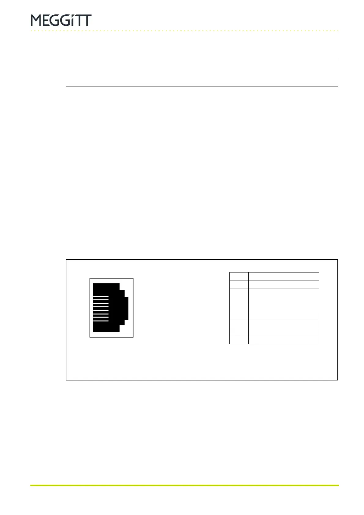
The pin connections (pinouts) for the 8-pin 8P8C (RJ45) connectors are shown in
Figure 13-14.
Figure 13-14: Pin definitions for the Ethernet connectors on the IOCN card
(1 and 2 connectors)
8
1
8P8C (RJ45) Ethernet
connector on the IOCN card
(female)
Pin Signal
1Tx+
2Tx−
3Rx+
4 Not connected
5 Not connected
6Rx−
7 Not connected
8 Not connected
Pin

 Loading...