HARDWARE MANUAL Document reference MAMPS-HW/E
VM600 machinery protection system (MPS) Edition 18 - March 2022
9-40
Grounding options
CONFIGURATION OF MPC4 / IOC4T CARDS
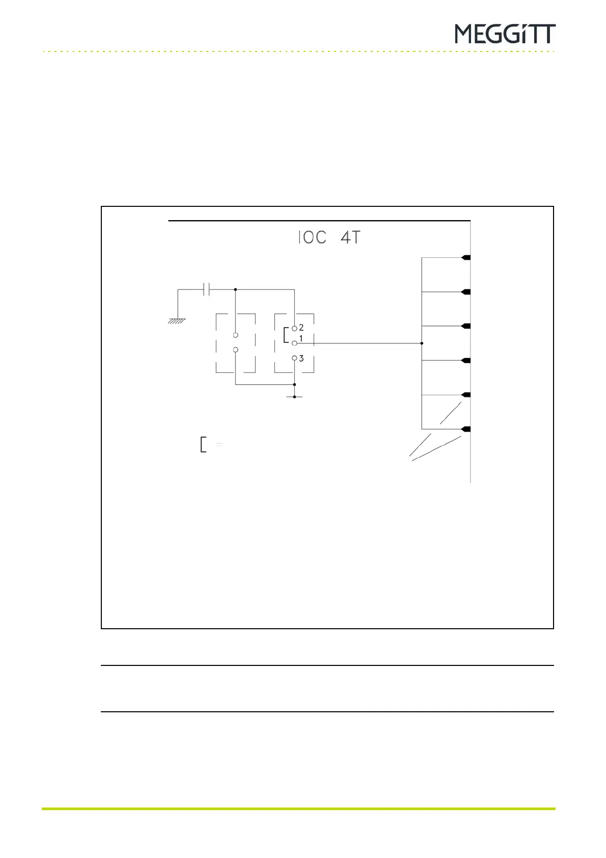
9.10Grounding options
Jumper J1015 on the IOC4T card (see Figure 9-28) allows the commoned (that is, connected
together) sensor shields to be connected to either:
• The case ground (chassis)
In this case, contacts 1-2 of J1015 must be shorted.
• The VME ground (0 V
A
)
In this case, contacts 1-3 of J1015 must be shorted.
The location of the J1015 jumper on the IOC4T card can be found using Figure 9-29.
NOTE: For the standard version of an ABE04x rack with the standard version of an MPC4
card installed, the case ground (rack chassis) is connected to the VME ground
(0 V
A
).
Figure 9-28: Jumper to configure grounding option
Measurement
channel 1
Measurement
channel 2
Measurement
channel 3
Measurement
channel 4
Speed
channel 1
Speed
channel 2
Sensor
shield
VME ground
(0 V
A
)
Case ground
(chassis)
Default (factory) setting
SHIELD inputs
(commoned together
on IOC4T card)
High-voltage
capacitor
*
Notes
The standard version of the IOC4T card has a jumper (short-circuit) between contacts 2-1 of J1015,
as shown above, and a short-circuit between contact 2 of J1015 and case ground (chassis). That is, the
high-voltage capacitor
* shown above is effectively replaced by a short-circuit.
The separate circuits version of the IOC4T card has no jumpers (short-circuits) between the contacts of J1015,
and a high-voltage capacitor
* between contact 2 of J1015 and case ground (chassis).
For both the standard and separate circuits versions of the IOC4T card, J1016 is reserved for system test and
should not be changed by the user.
J1015J1016
 Loading...
