HARDWARE MANUAL Document reference MAMPS-HW/E
VM600 machinery protection system (MPS) Edition 18 - March 2022
2-48
RPS6U rack power supply (ABE04x only)
OVERVIEW OF VM600 MPS HARDWARE
3- When only the second RPS6U (PS2) is installed (slots 15 to 17):
• Jumper J16 must be closed
• Jumper J17 must be left open.
4- When both RPS6Us (PS1 and PS2) are installed:
• Jumper J16 must be left open
• Jumper J17 must be left open.
2.10.11 Power supply labelling
Information regarding the DC and AC inputs for the RPS6U rack power supplies used by a
VM600 system rack (ABE04x) is available as follows:
• For later versions of VM600 system racks:
• Input labels close to the input connectors on the associated rear panels provide the
specifications for the RPS6U power supply inputs (see 2.10.9 Associated rear
panels).
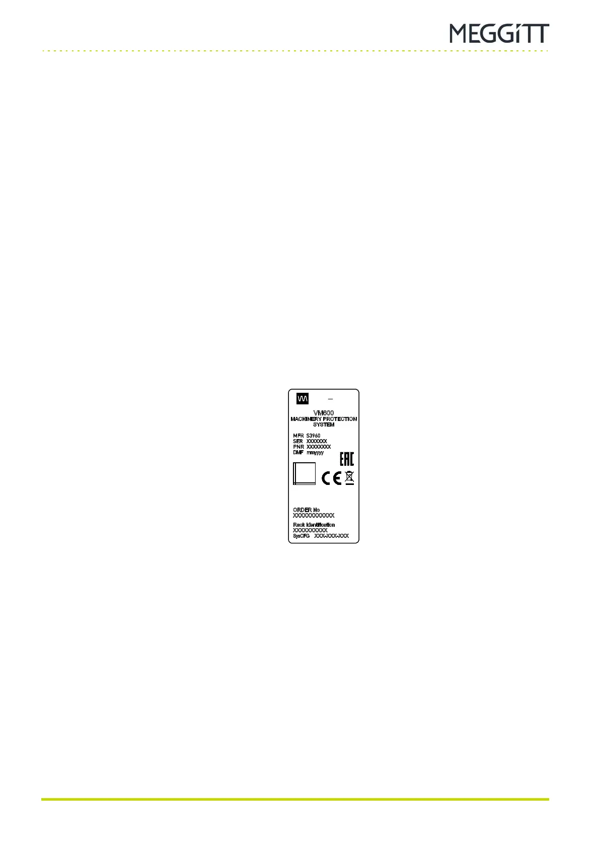
• A VM600SYS label on a rear panel provides additional information about the VM600
system such as order number and system configuration (SysCFG) number
(see Figure 2-31).
• For earlier versions of VM600 system racks, a VM600SYS label on a rear panel provides
the specifications for the RPS6U power supply inputs and additional information about
the VM600 system such as order number (see Figure 2-32).
Figure 2-31: Example VM600SYS label (later versions of VM600 system racks)
vibro
meter
DATA
MATRIX
2D
 Loading...
