HARDWARE MANUAL Document reference MAMPS-HW/E
VM600 machinery protection system (MPS) Edition 18 - March 2022
9-14
Connecting vibration and pressure sensors
CONFIGURATION OF MPC4 / IOC4T CARDS
9.2.4 Connection diagrams for externally powered hardware
9.2.4.1 Voltage-modulated signal with GSI127 galvanic separation unit
Applies to the later versions of the following transducers or transducer and signal conditioner
systems:
• CAxxx + IPC70x + GSI127 galvanic separation unit
• CE1xx + GSI127 galvanic separation unit
• CE3xx + GSI127 galvanic separation unit
• CPxxx + IPC70x + GSI127 galvanic separation unit
• TQ4xx + IQS45x + GSI127 galvanic separation unit.
Notes
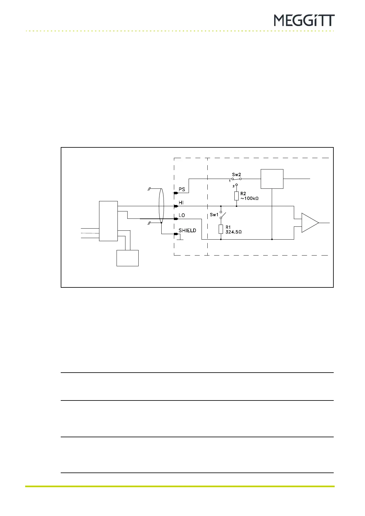
1- Switch Sw1 is open to allow voltage-modulated signals to be processed.
The Signal Transmission Mode field has to be set to the Voltage option.
2- Switch Sw2 must be set to position 1. This connects the IOC4T card's sensor power
supply to the PS terminal, though in fact this terminal is not used.
The Sensor Power Supply field can be set to any option (+27 VDC, −27 VDC, +15 VDC
or +6.16 mA).
NOTE: Do not set the Sensor Power Supply field to No Supply. This option is reserved
for unpowered sensors and will cause Sw2 to go to position 2, thus putting 27.2 V
on the HI terminal.
3- The operator must connect an external power supply to terminals “24 VDC +” and
“24 VDC −” of the GSI127 galvanic separation unit.
NOTE: More detailed information on connecting equipment to an electronic monitoring
system can be found in the project-specific wiring diagram delivered with the
system or by referring to the electrical connections (wiring diagrams) section of the
appropriate sensors and signal conditioners installation manual.
Figure 9-8: Connection diagram
Sensor
power
supply
External
power
supply
O/P
0V
(−)
+
SIGNAL24 VDC
GSI127
I/P
−/COM
+/COM
From sensor (transducer)
or measurement chain
IOC4T MPC4
−
(+)

 Loading...