Document reference MAMPS-HW/E HARDWARE MANUAL
Edition 18 - March 2022 VM600 machinery protection system (MPS)
10 - 7
Connecting sensors to the IOC8T
CONFIGURATION OF AMC8 / IOC8T CARDS
10.2.2 Connecting thermocouples
The operating principle of a thermocouple (TC) is based on the Seebeck effect. If two
dissimilar metal wires are soldered together at one end (the “hot” junction), a voltage in the
mV range will be generated across the free ends (the “cold” junction). This voltage is
proportional to the difference in temperature between the hot and cold junctions. The
temperature of the cold junction should be measured by another sensor (preferably a RTD
device) and this signal is then used for compensation purposes. This technique is known as
cold-junction compensation (CJC).
The hot junction is placed at the measuring point. The cold junction should ideally be on a
terminal strip placed in an isothermal box, that is, one in which there is a negligible
temperature difference between the junctions on the terminal pins, creating a negligible
voltage error.
Another temperature sensor measures the internal temperature of the box, near the terminal
strip. This is processed by another channel on the AMC8 card and used for cold junction
compensation (2 out of the 8 channels on the AMC8 can be configured for CJC purposes
using the VM600 MPSx software).
When cold-junction compensation (CJC) is used with a thermocouple (TC) device,
temperature offsets can arise between the resistance temperature detector (RTD) device
used for CJC and the thermocouple input connections if there are large temperature
differences between the inside and outside of the VM600 rack. (Temperature offsets of up to
10°C (18°F) have been reported in extreme cases.)
In practice, the temperature inside of a VM600 rack can be higher than the temperature
outside, where the CJC RTD is installed, and the heat inside of the rack can be transmitted
to the screw-terminal connectors that connect to the thermocouple (TC), leading to an error
in reported temperature measurements that is proportional to the temperature offset.
Accordingly, when cold-junction compensation (CJC) is used with a thermocouple (TC)
device, temperature differences around a VM600 rack should be minimised, for example, by
using forced-air cooling (such as a rack-mounted fan below IOC8T cards) or a
temperature-controlled environment.
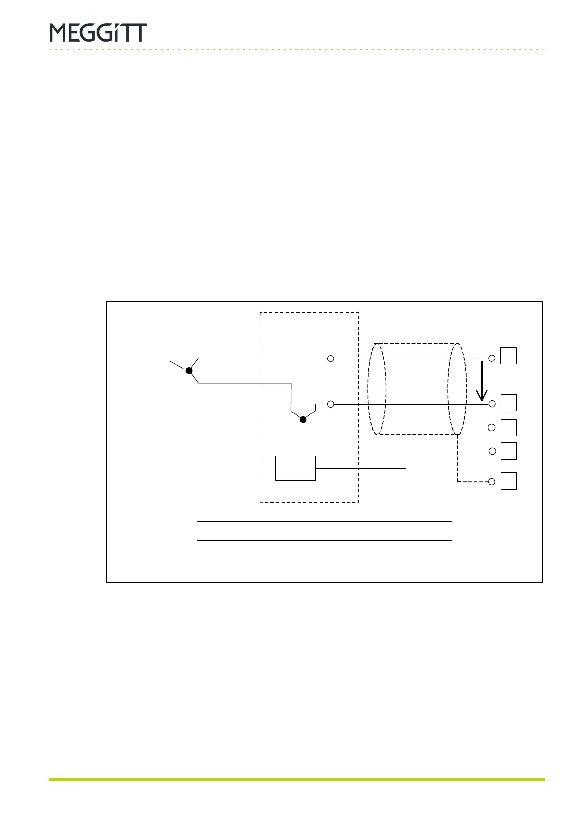
Figure 10-4: Wiring for thermocouple with CJC
Thermocouple
T
hot
T
cold
Isothermal box
Metal “B”
Metal “A”
Connect to
CJC channel
Note: Usually the cold
junction is merged with the
lower terminal (shown here
as a “white dot”).
The representation shown
here is simply for clarity.
Hot junction
NOTE: The setting of jumper J805 is unimportant.
 Loading...
