Document reference MAMPS-HW/E HARDWARE MANUAL
Edition 18 - March 2022 VM600 machinery protection system (MPS)
2-15
CPUM modular CPU card (ABE04x only)
OVERVIEW OF VM600 MPS HARDWARE
2.6 CPUM modular CPU card (ABE04x only)
See Figure 2-12 for details on the physical appearance of this card.
2.7 IOCN input/output card (ABE04x only)
See Figure 2-13 for details on the physical appearance of this card.
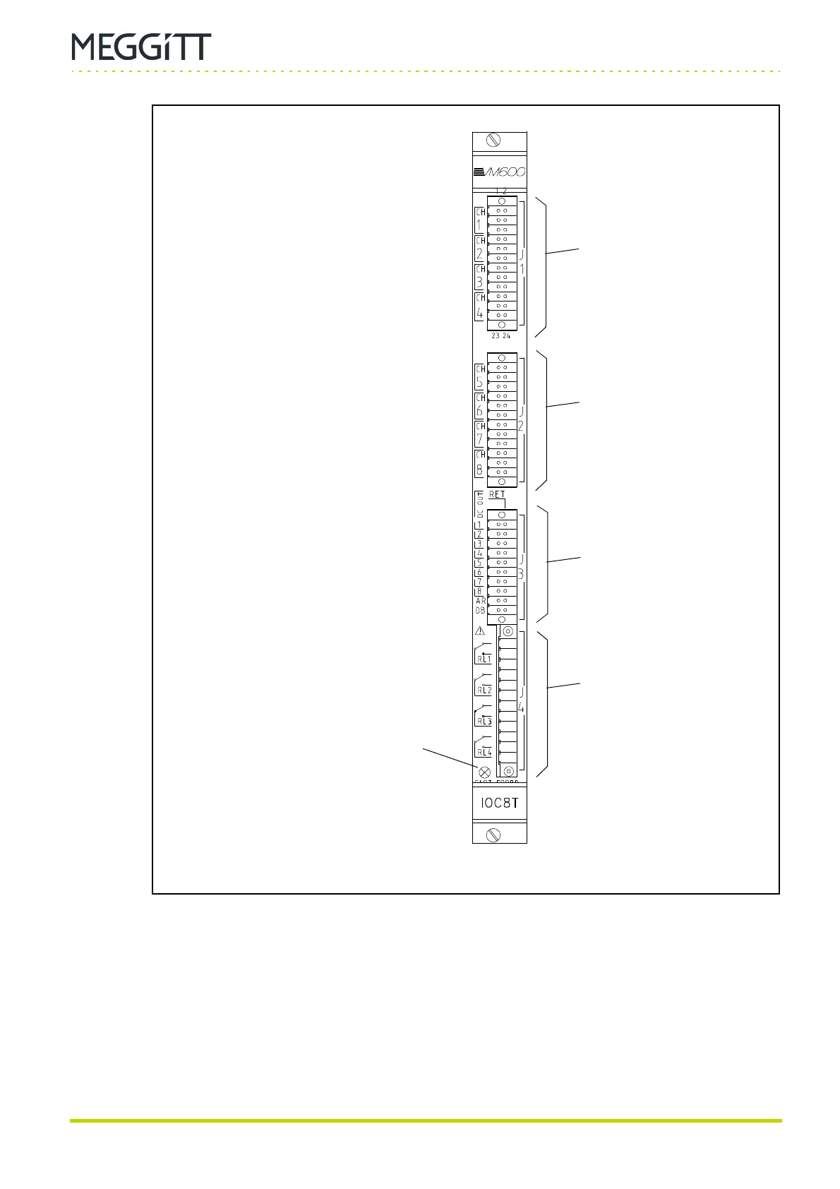
Figure 2-11: IOC8T panel (rear of ABE04x and ABE056 racks)
SLOT ERROR indicator
The colour of this LED indicates whether the
IOC8T is installed in the correct slot of the
rack:
Green – The card is in the correct slot
Red – Slot number mismatch.
Connector J1
(mating connector with 24
cage clamp terminals)
Connector J2
(mating connector with 24
cage clamp terminals)
Connector J3
(mating connector with 20
cage clamp terminals)
Connector J4
(mating connector with
12 screw terminals)

 Loading...