HARDWARE MANUAL Document reference MAMPS-HW/E
VM600 machinery protection system (MPS) Edition 18 - March 2022
7-26
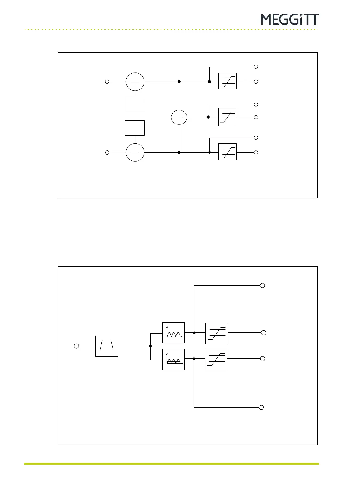
Broad-band pressure monitoring
PROCESSING MODES AND APPLICATIONS
2) Block diagram
The difference in expansion measured on each side of the machine is calculated as follows:
ΔX = (X1
− Initial GAP1) − (X2 − Initial GAP2)
7.12Broad-band pressure monitoring
X1 input
Figure 7-22: Block diagram showing differential housing expansion processing
X1 value
Alarm level
detectors
Initial
gap 1
X2 input
Initial
gap 2
X1 alarms
X1−X2 value
X1−X2 alarms
X2 value
X2 alarms
Pressure
input
Broad band
Output 1
pressure alarm
Output 2
pressure alarm
Output 2
pressure value
Output 1
pressure value
RMS (+ scaled values)
Mean
Peak
Peak-Peak
Alarm level
detector
Figure 7-23: Block diagram showing broad-band pressure processing
Alarm level
detector
 Loading...
