Document reference MAMPS-HW/E HARDWARE MANUAL
Edition 18 - March 2022 VM600 machinery protection system (MPS)
13 - 1
Configuring Ethernet communications
CONFIGURATION OF CPUM / IOCN CARDS
13 CONFIGURATION OF CPUM / IOCN CARDS
Jumpers on the CPUM and IOCN cards are used to configure the external communications
interfaces.
Refer also to the block diagrams in 6 CPUM / IOCN card pair (Figures 6-1, 6-2, 6-3 and 6-4).
NOTE: The location of the jumpers on the CPUM card can be found using Figure 13-16 or
Figure 13-17.
The location of the jumpers on the IOCN card can be found using Figure 13-18.
13.1Configuring Ethernet communications
Primary Ethernet communications can be routed via either the ‘NET’ connector on the CPUM
card’s panel or the ‘1’ connector on the IOCN card’s panel.
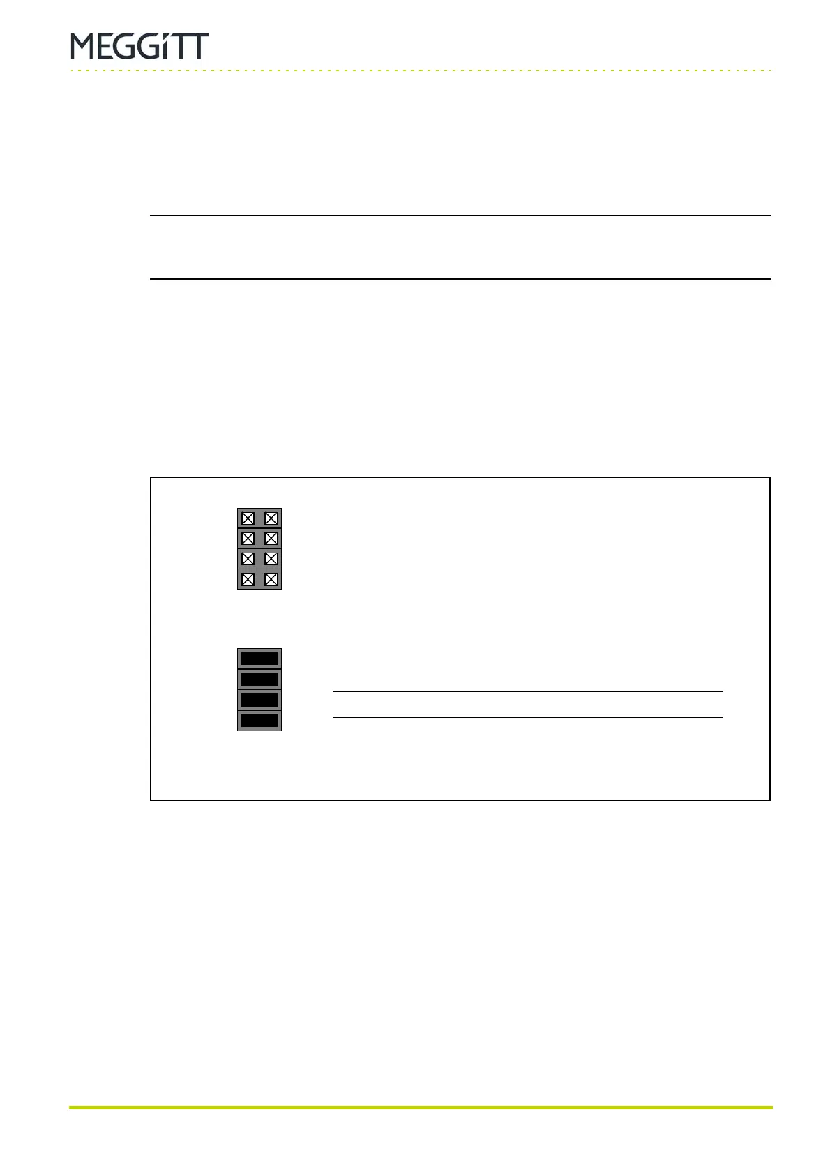
The choice is made using jumpers J42, J40, J52 and J53 on the CPUM card.
The location of the jumpers on the CPUM card can be found using Figure 13-16 or
Figure 13-17.
(b) The 1 Ethernet connector on panel of IOCN is selected
NOTE: This is the default factory setting.
(a) The NET Ethernet connector on panel of CPUM is selected
J42
J40
J52
J53
J42
J40
J52
J53
Figure 13-1: CPUM card jumper settings to select the Ethernet connector
 Loading...
