EasyManuals Logo

Meggitt vibro-meter VM600 User Manual

Meggitt vibro-meter VM600
382 pages
To Next Page IconTo Next Page
To Previous Page IconTo Previous Page
Page #245 background imageLoading...
Page #245 background image
Document reference MAMPS-HW/E HARDWARE MANUAL
Edition 18 - March 2022 VM600 machinery protection system (MPS)
9-29
Connecting speed sensors
CONFIGURATION OF MPC4 / IOC4T CARDS
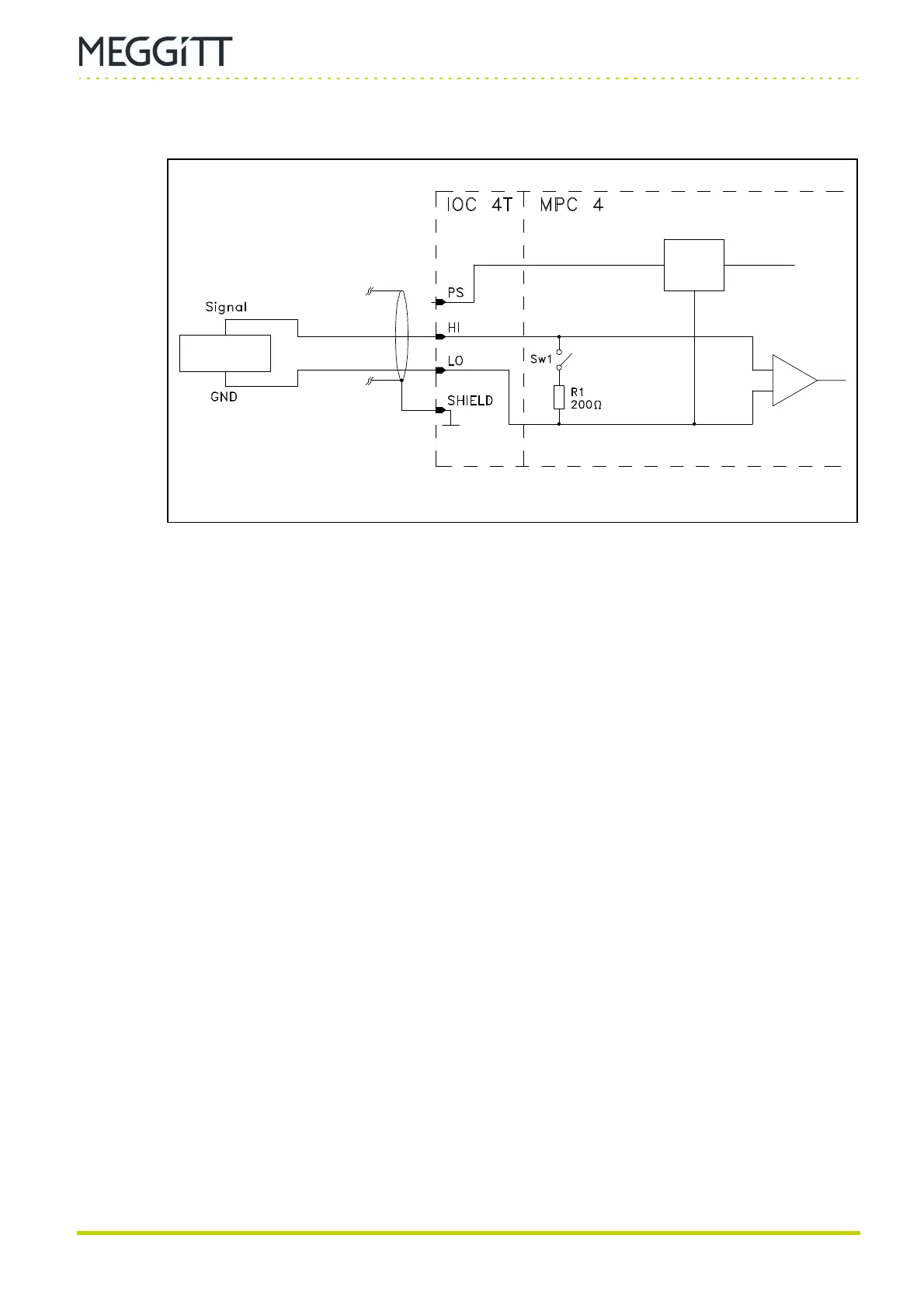
9.3.5 Connection diagram for frequency generator
Notes
1- Switch Sw1 is open to allow voltage-modulated signals to be processed.
The Signal Transmission Mode field has to be set to the Voltage option.
2- The sensor power supply is always set to −27.2 V.
Figure 9-22: Connection diagram
Sensor
power
supply
SPEED
INPUT
Frequency
generator
(−27.2 V only)

Table of Contents

Other manuals for Meggitt vibro-meter VM600

Questions and Answers:

Question and Answer IconNeed help?

Do you have a question about the Meggitt vibro-meter VM600 and is the answer not in the manual?

Meggitt vibro-meter VM600 Specifications

General IconGeneral
BrandMeggitt
Modelvibro-meter VM600
CategoryProtection Device
LanguageEnglish