HARDWARE MANUAL Document reference MAMPS-HW/E
VM600 machinery protection system (MPS) Edition 18 - March 2022
9-30
Configuring the four local relays on the IOC4T
CONFIGURATION OF MPC4 / IOC4T CARDS
9.4 Configuring the four local relays on the IOC4T
Connector J2 of the IOC4T card has terminals for the following four relay outputs:
• RL1 – Pins 9 and 10 on connector J2
• RL2 – Pins 11 and 12 on connector J2
• RL3 – Pins 13 and 14 on connector J2
• RL4 – Pins 15 and 16 on connector J2.
Specific alarms can be attributed to these relays using the VM600 MPSx software.
NOTE: Refer to the relevant manual for further information: VM600 MPS1 software
manual or VM600 MPS2 software manual.
Specific alarms (A+, D− and so on) generated by an MPC4 card can be selected as control
signals for these local relays using the VM600 MPSx software. The control signals are
generally low in the absence of an alarm, that is, in a “normal” state (which means that the
control signal is high-impedance), although there are exceptions to this rule as shown in
Table 9-4.
In the event of an alarm, the appropriate control signal changes state (which generally means
that the control signal is pulled low to ground).
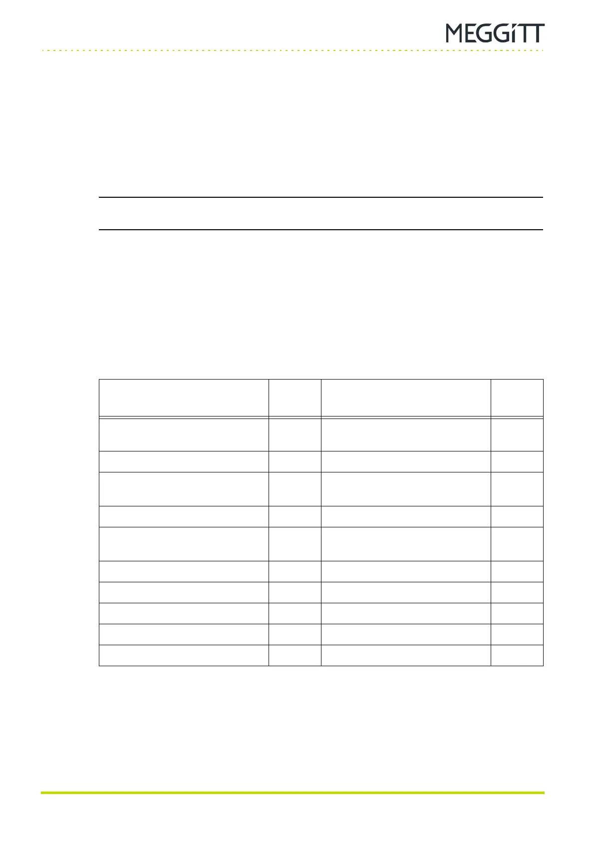
Table 9-4: Normal state of “control signals” (in absence of alarm condition)
Parameter
Normal
state
Parameter
Normal
state
Common OK (Common OK alarm
level)
0 DSP Saturation Error 0
Individual OK 1 Status Latched (Error Log) 0
Common Alert (Common Alert
alarm level)
0 Input Signal Error 0
Individual Alert 0 Input Saturation Error 0
Common Danger (Common
Danger alarm level)
0 Common Mode Range Overflow 0
Individual Danger 0 Invalid Output 0
TM, DB, AR 0 Speed Out Of Limit 0
MPC Card Running 1 Track Lost 0
Common Monitoring Failure 0 Track Out Of Range 0
Processing Error 0 PGA Saturation Error 0
Key: 0 = control signal in low state, 1 = control signal in high state.
 Loading...
