3 x screw terminal strip (J1, J2 and J3)
Front
panel
BNCs
MPC4
panel
DIAG/
STATUS
Channel
status
Rack backplane
RLC16
MPC4
IOC4T
(Front card cage)
(Rear card cage)
(Rear card cage)
Relay card with 16 change-over contacts
Relays
3 x screw
terminal strip
(J1, J2, J3)
EMC prot.EMC prot.EMC prot.
EMC
prot.
EMC
prot.
EMC
prot.
EMC
prot.
EMC
prot.
Buffer Buffer
Raw meas. signal
(Filtering,
integration,
rectification)
(Monitoring,
configuration)
RS-232
(Gain,
anti-alias, etc.)
ADC
DSP
Micro-
Controller
Digital
speed
chan. SW
Analog
speed
channels
Analog
meas.
channels
Sensor
power
supply
IP
interface
VME
interface
9-pin
D-sub
connector
(RS-232)
Front
panel
BNCs
VME bus
(see notes)
Raw Bus
(to other
cards)
Tacho Bus
(to/from
other cards)
Raw signal and
OC selection
(jumper matrix)
TTL
OC
Bus
Local
relays
Switch
input
decoder
IP
Interface
4-channel
DAC
Speed
channel
selection
U/I
conv.
JS
Open
collector
driver
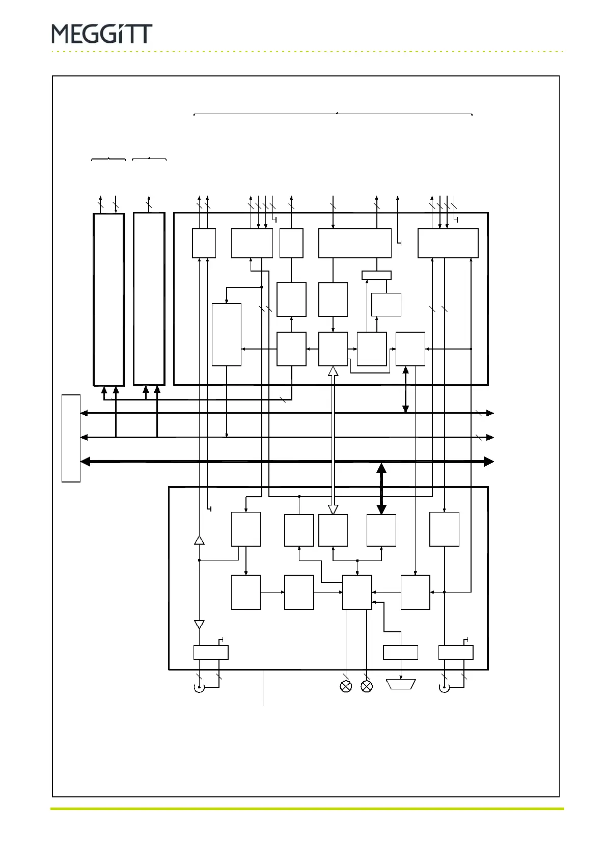
Figure 4-2: Block diagram of MPC4, IOC4T, RLC16 and IRC4 cards
Abbreviations:
ADC = Analog-to-digital converter, AR = Alarm Reset, DAC = Digital-to-analog converter,
DB = Danger Bypass, DSP = Digital signal processor,
EMC = Electromagnetic compatibility, IP = Industry pack, I/P = Input,
JS = Jumper selectable, OC = Open Collector, TM = Trip Multiply,
SW = Software, VME = VERSAbus module eurocard.
Vib. Raw (H)
Vib. Raw (L)
Meas. sensors
Sensor Power
Sensor I/P (Hi)
Sensor I/P (Lo)
Shield
Speed Sensors
Sensor Power
Sensor I/P (Hi)
Sensor I/P (Lo)
Shield
RL1, RL2,
RL3 and RL4
DB
TM
AR
DC OUT
0to10V or
4to20mA (JS)
RET
IRC4
(Rear card cage)
Intelligent relay card with 4 DPDT or 8 SPDT
0 to 10 V
4 to
20 mA
4
4
1
6
2
2
64 8
16
2x2
2
2
4x2
2
2
2
2
4
3
4
4
4
4
4
4
4
16x3
6
8x3
Relays
DSI
2 x screw
terminal strip
(J1, J2)
Notes:
The safety version of the MPC4 card (MPC4SIL) does
not have a VME bus interface.
The ABE056 does not have a VME bus.
 Loading...
