HARDWARE MANUAL Document reference MAMPS-HW/E
VM600 machinery protection system (MPS) Edition 18 - March 2022
9-12
Connecting vibration and pressure sensors
CONFIGURATION OF MPC4 / IOC4T CARDS
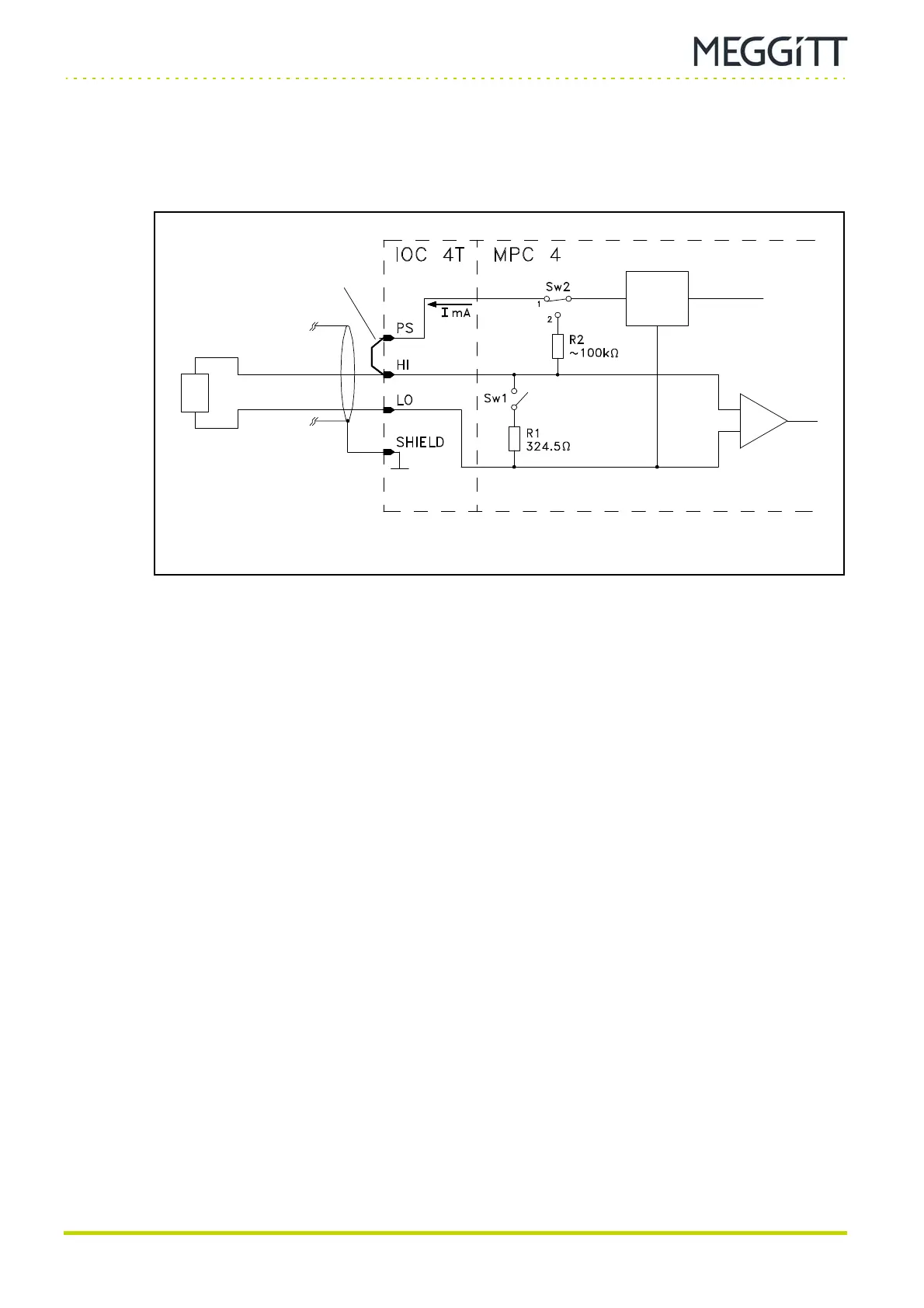
9.2.2.3 Constant current power supply and voltage-modulated signal
Applies to the following transducers:
•CE6xx.
Notes
1- Switch Sw1 is open to allow voltage-modulated signals to be processed.
For non-vibro-meter devices, the Signal Transmission Mode field has to be set to the
Voltage option.
2- Switch Sw2 is set to position 1 to connect the IOC4T card's sensor power supply to the
PS terminal.
For non-vibro-meter devices, the Sensor Power Supply field has to be set to a current
option.
3- An external link must be made between the PS and HI terminals.
4- The standing current value is 6.16 mA.
Figure 9-6: Connection diagram
Sensor
power
supply
External link
 Loading...
