HARDWARE MANUAL Document reference MAMPS-HW/E
VM600 machinery protection system (MPS) Edition 18 - March 2022
10 - 4
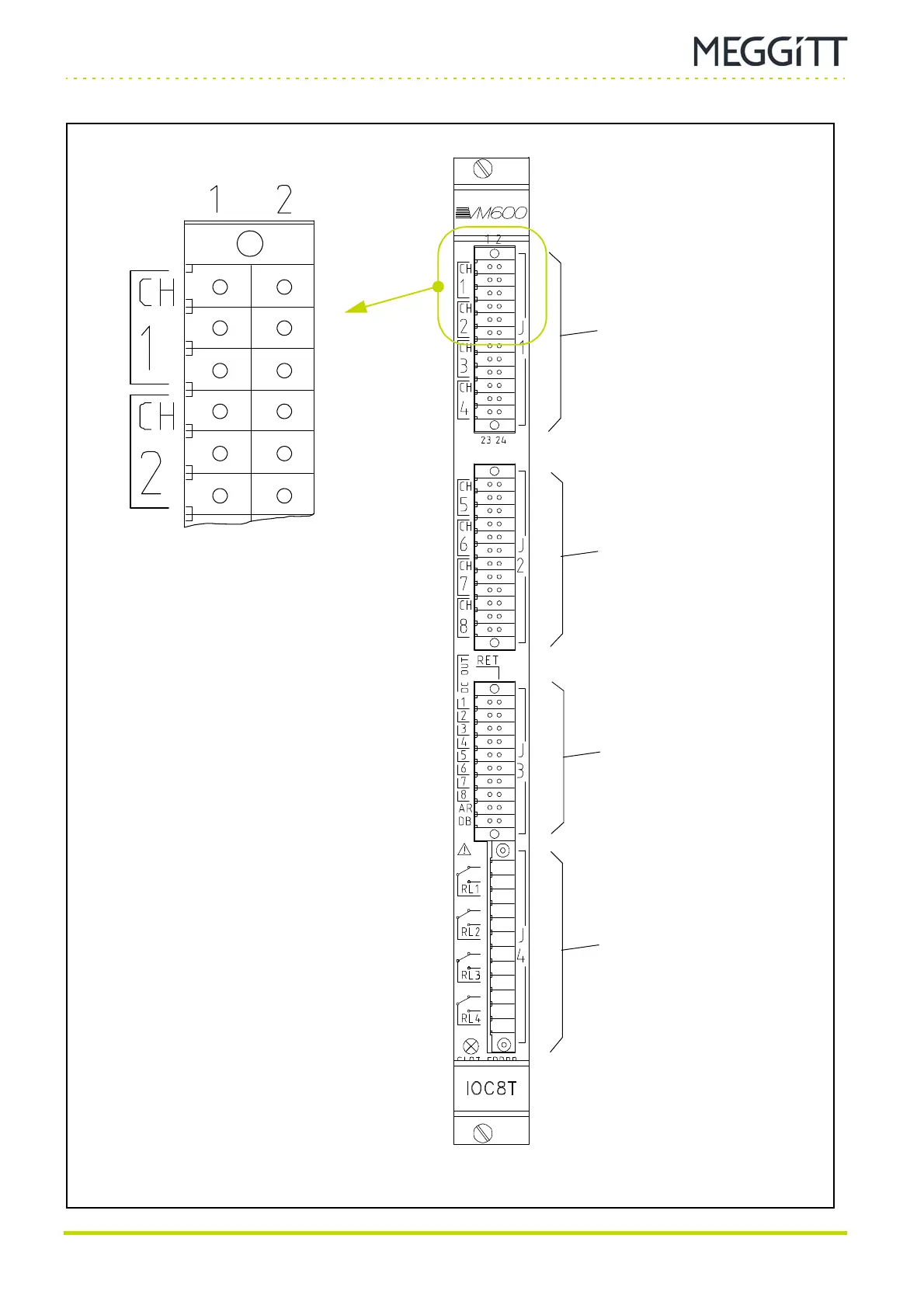
Definition of screw terminals on the IOC8T card
CONFIGURATION OF AMC8 / IOC8T CARDS
(1)
(3)
(5)
(7)
(9)
(11)
(2)
(4)
(6)
(8)
(10)
(12)
I
R
S
I
R
S
H
C
Gnd
H
C
Gnd
Figure 10-1: View of IOC8T card showing definition of terminals (without mating connectors)
Connector J1
(mating connector with 24
cage clamp terminals)
Connector J2
(mating connector with 24
cage clamp terminals)
Connector J4
(mating connector with
12 screw terminals)
Connector J3
(mating connector with 20
cage clamp terminals)
Refer also to Table 10-1
for full pin definitions
 Loading...
