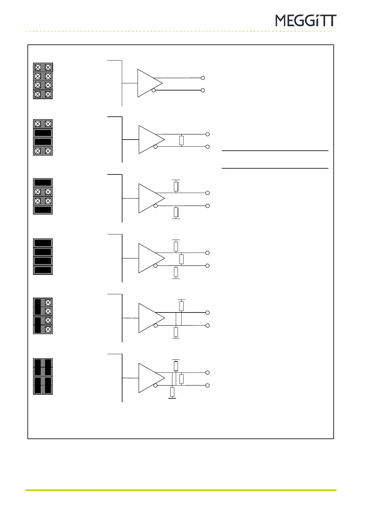
Figure 13-12: Jumper settings for various types of RS-485 terminations
(PNR 200-595-510-110 serial communications module)
J31_x
J32_x
J33_x
J34_x
J31_x
J32_x
J33_x
J34_x
J31_x
J32_x
J33_x
J34_x
J31_x
J32_x
J33_x
J34_x
J31_x
J32_x
J33_x
J34_x
J31_x
J32_x
J33_x
J34_x
(a) Not terminated
Line driver connects directly to the
differential pair.
(b) Terminated
Differential pair is terminated with 120 Ω
resistance between the signal lines.
(c) Pulled inactive
Differential pair is pulled apart to mimic no
character being transmitted from UART.
(d) Pulled inactive and terminated
Differential pair is terminated with 120 Ω and
is pulled apart to mimic no character being
transmitted.
(e) Pulled active
Differential pair is pulled apart to mimic
UART sending a break condition.
(f) Pulled active and terminated
Differential pair is terminated with 120 Ω and
is pulled apart to mimic a break condition.
 Loading...
